Watchdog timer UM0404
298/564 DocID13284 Rev 2
14.1 Operation of the watchdog timer
The current count value of the watchdog timer is contained in the Watchdog Timer Register
WDT, which is a bit-addressable read-only register. The operation of the Watchdog Timer is
controlled by its bit-addressable Watchdog Timer Control Register WDTCON. This register
specifies the reload value for the high byte of the timer, selects the input clock prescaling
factor and provides a flag that indicates a watchdog timer overflow.
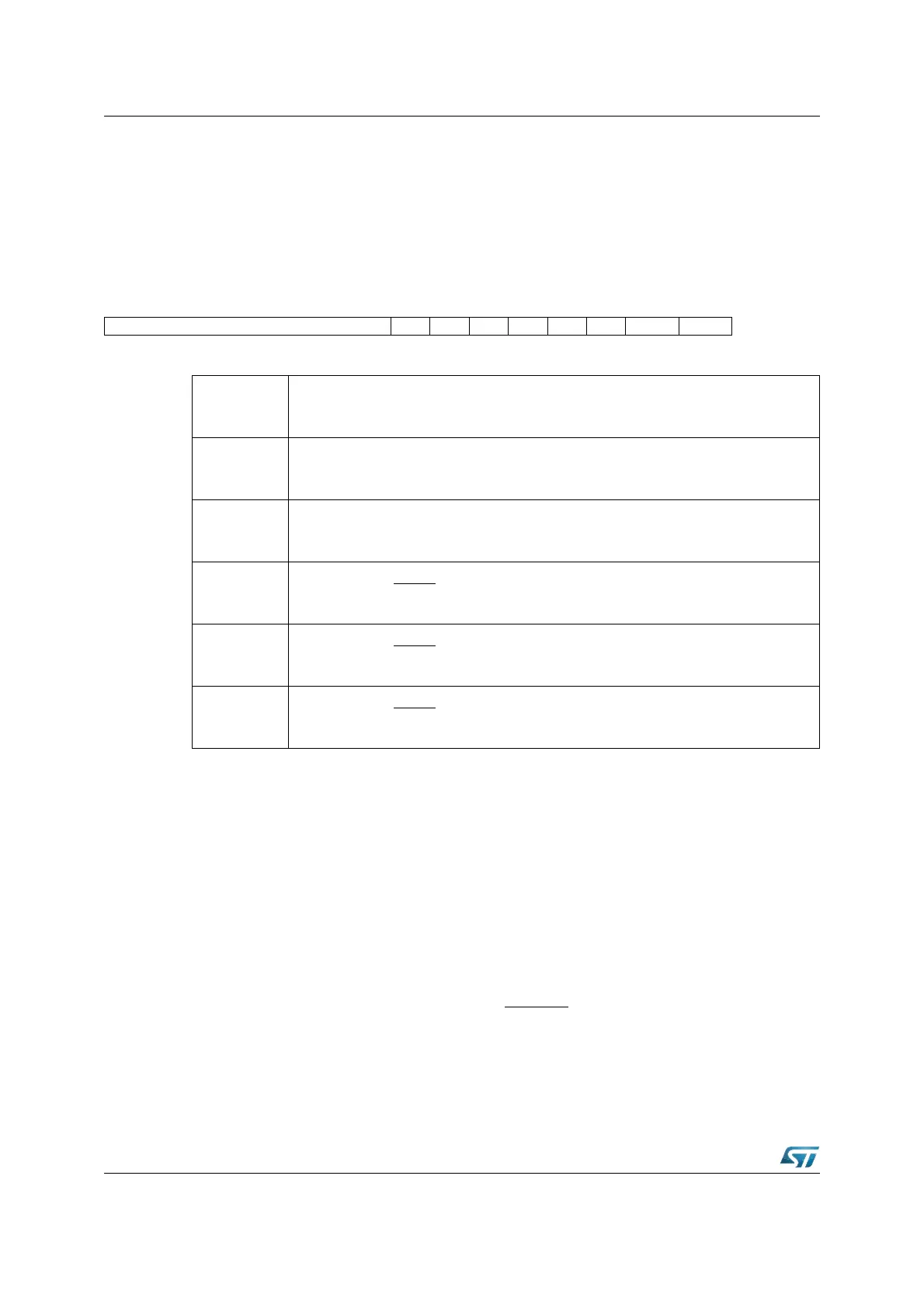
WDTCON (FFAEh / D7h) SFR Reset Value: 00xxh
After any software reset, external hardware reset (see note), or watchdog timer reset, the
watchdog timer is enabled and starts counting up from 0000h with the frequency f
CPU
/2.
The input frequency may be switched to f
CPU
/ 128 by setting bit WDTIN. The watchdog
timer can be disabled via the instruction DISWDT (Disable Watchdog Timer). Instruction
DISWDT is a protected 32-bit instruction which will ONLY be executed during the time
between a reset and execution of either the EINIT (End of Initialization) or the SRVWDT
(Service Watchdog Timer) instruction. Either one of these instructions disables the
execution of DISWDT.
When the watchdog timer is not disabled via instruction DISWDT, it will continue counting
up, even during Idle Mode. If it is not serviced via the instruction SRVWDT by the time the
count reaches FFFFh the watchdog timer will overflow and cause an internal reset. This
reset will pull the external reset indication pin RSTOUT
low. It differs from a software or
external hardware reset in that bit WDTR (Watchdog Timer Reset Indication Flag) of register
WDTCON will be set. A hardware reset or the SRVWDT instruction will clear this bit. Bit
WDTR can be examined by software in order to determine the cause of the reset.
15141312111098765432 1 0
WDTREL - - PONR LHWR SHWR SWR WDTR WDTIN
RW RW RW RW RW RW RW
WDTIN
Watchdog Timer Input Frequency Selection
‘0’: Input Frequency is f
CPU
/2 (Default after Reset).
‘1’: Input Frequency is f
CPU
/128.
WDTR
(1)
1. More than one reset indication flag may be set. After EINIT, all flags are cleared.
Watchdog Timer Reset Indication Flag
Set by the watchdog timer on an overflow.
Cleared by a hardware reset or by the SRVWDT instruction.
SWR
(1)
Software Reset Indication Flag
Set by the SRST execution.
Cleared by the EINIT instruction.
SHWR
(1)
Short Hardware Reset Indication Flag
Set by the input RSTIN.
Cleared by the EINIT instruction.
LHWR
(1)
Long Hardware Reset Indication Flag
Set by the input RSTIN.
Cleared by the EINIT instruction.
PONR
(1) - (2)
2. Power-on is detected when a rising edge from V
DD
= 0 V to V
DD
> 2.0 V is recognized.
Power-On (Asynchronous) Reset Indication Flag
Set by the input RSTIN
if a Power-On condition has been detected.
Cleared by the EINIT instruction.