The general purpose timer units UM0404
234/564 DocID13284 Rev 2
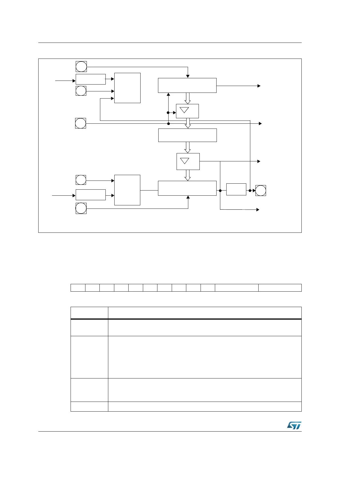
Figure 90. GPT2 block diagram
9.2.1 GPT2 core timer T6
The operation of the core timer T6 is controlled by its bit-addressable control register
T6CON.
T6CON (FF48h / A4h) SFR Reset Value: 0000h
2
n
n=2...9
2
n
n=2...9
T5EUD
T5IN
CPU Clock
CPU Clock
T6IN
T6EUD
T5
Mode
T6
Mode
GPT2 Timer T5
GPT2 Timer T6
U/D
Interrupt
Request
Up/Down
GPT2 CAPREL
T6OTL
T6OUT
CAPIN
Reload
Interrupt
Request
to CAPCOM
Timers
Capture
Clear
Interrupt
Request
P5.11
P5.13
P5.12
P3.2
P5.10
P3.1
T0, T1, T7, T8
15 14 13 12 11 10 9 8 7 6 5 4 3 2 1 0
T6SR----T6OTL T6OE T6UDE T6UD T6R T6M T6I
RW RW RW RW RW RW RW RW
Bit Function
T6I
Timer 6 Input Selection
Depends on the Operating Mode, see respective sections.
T6M
Timer 6 Mode Control (Basic Operating Mode)
0 0 0: Timer Mode
0 0 1: Counter Mode
0 1 0: Gated Timer with Gate active low
0 1 1: Gated Timer with Gate active high
1 X X: Reserved. Do not use this combination.
T6R
Timer 6 Run bit
T6R = ‘0’:Timer / Counter 6 stops
T6R = ‘1’:Timer / Counter 6 runs
T6UD Timer 6 Up / Down Control
(1)