Interrupt and trap functions UM0404
110/564 DocID13284 Rev 2
5.5 Interrupt response times
The interrupt response time defines the time from an interrupt request flag of an enabled
interrupt source being set until the first instruction (I1) being fetched from the interrupt vector
location. The basic interrupt response time for the ST10F276 is three instruction cycles (see
Figure 22).
All instructions in the pipeline including instruction N (during which the interrupt request flag
is set) are completed before entering the service routine. The actual execution time for
these instructions (wait-states) therefore influences the interrupt response time.
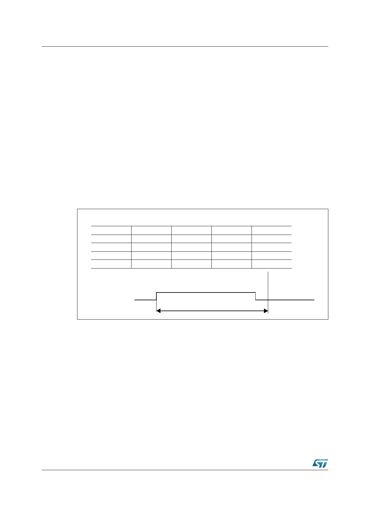
In the Figure 22 the respective interrupt request flag is set in cycle 1 (fetching of instruction
N). The indicated source wins the prioritization round (during cycle 2). In cycle 3 a TRAP
instruction is injected into the decode stage of the pipeline, replacing instruction N+1 and
clearing the source's interrupt request flag to '0'. Cycle 4 completes the injected TRAP
instruction (save PSW, IP and CSP, if segmented mode) and fetches the first instruction (I1)
from the respective vector location.
All instructions that entered the pipeline after setting of the interrupt request flag (N+1, N+2)
will be executed after returning from the interrupt service routine.
Figure 22. Pipeline diagram for interrupt response time
The minimum interrupt response time is five CPU clock cycles. This requires program
execution from the internal Flash, no external operand read requests and setting the
interrupt request flag during the last CPU clock cycle of an instruction. When the interrupt
request flag is set during the first CPU clock cycle of an instruction, the minimum interrupt
response time is six CPU clock cycles.
The interrupt response time is increased by all delays of the instructions in the pipeline that
are executed before entering the service routine (including N).
• When internal hold conditions between instruction pairs N-2/N-1 or N-1/N occur, or
instruction N explicitly writes to the PSW or the SP, the minimum interrupt response
time may be extended by one CPU clock cycle for each of these conditions.
• When instruction N reads an operand from the internal memory, or when N is a CALL,
RETURN, TRAP, or MOV Rn, [Rm+ #data16] instruction, the minimum interrupt
response time may additionally be extended by two CPU clock cycles during internal
Flash program execution.
Pipeline Stage Cycle 1 Cycle 2 Cycle 3 Cycle 4
FETCH N N + 1 N + 2 I1
DECODE N - 1 N TRAP (1) TRAP (2)
EXECUTE N - 2 N - 1 N TRAP
WRITEBACK N - 3 N - 2 N - 1 N
Interrupt Response Time
1
0
IR-Flag