CAN modules UM0404
418/564 DocID13284 Rev 2
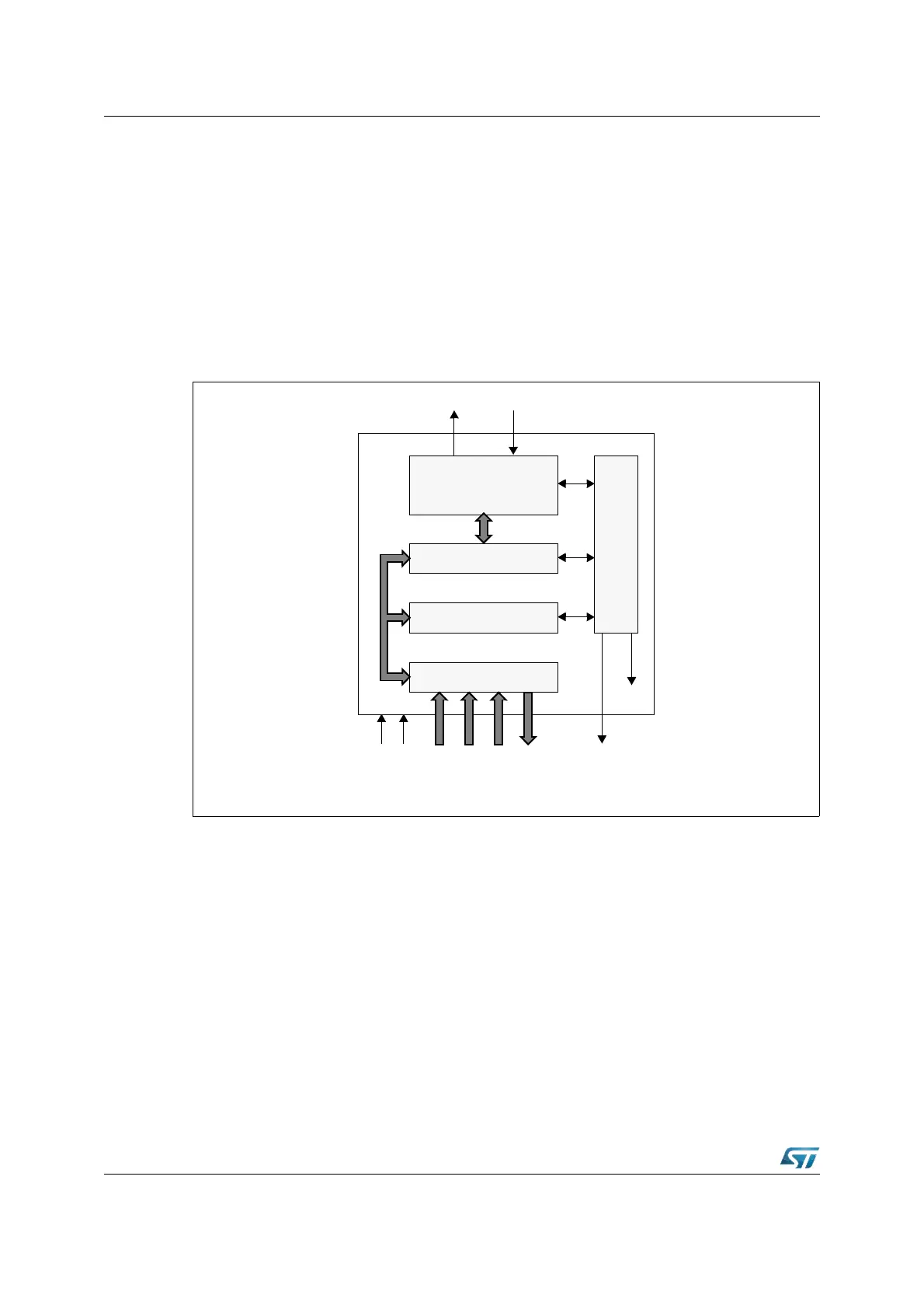
21.6 Block diagram
The module consists of the following functional blocks (see Figure 176):
• CAN Core: CAN Protocol Controller and Rx/Tx Shift Register for serial/parallel
conversion of messages.
• Message RAM: Stores Message Objects and Identifier Masks.
• Registers: All registers used to control and to configure the C-CAN module.
• Message Handler: State Machine that controls the data transfer between the Rx/Tx
Shift Register of the CAN Core and the Message RAM as well as the generation of
interrupts as programmed in the Control and Configuration Registers.
Figure 176. Block diagram of the C-CAN
21.7 Operating modes
21.7.1 Software initialization
The software initialization is started by setting the bit Init in the CAN Control Register, either
by software or by a hardware reset, or by going Bus_Off.
While Init is set, all message transfer from and to the CAN bus is stopped, the status of the
CAN bus output CAN_TxD is recessive (HIGH). The counters of the Error Management
Logic are unchanged. Setting Init does not change any configuration register.
To initialize the CAN Controller, the CPU has to set up the Bit Timing Register and each
Message Object. If a Message Object is not needed, it is sufficient to set its MsgVal bit to
not valid. Otherwise, the whole Message Object has to be initialized.
C-CAN
CAN Core
Registers
Module Interface
Message Handler
CAN_TxD CAN_RxD
Message RAM
DataIN
Interrupt
Clock
Reset
Address(7:0)
Control
CAN_WAIT_B
DataOUT