Pulse width modulation module UM0404
350/564 DocID13284 Rev 2
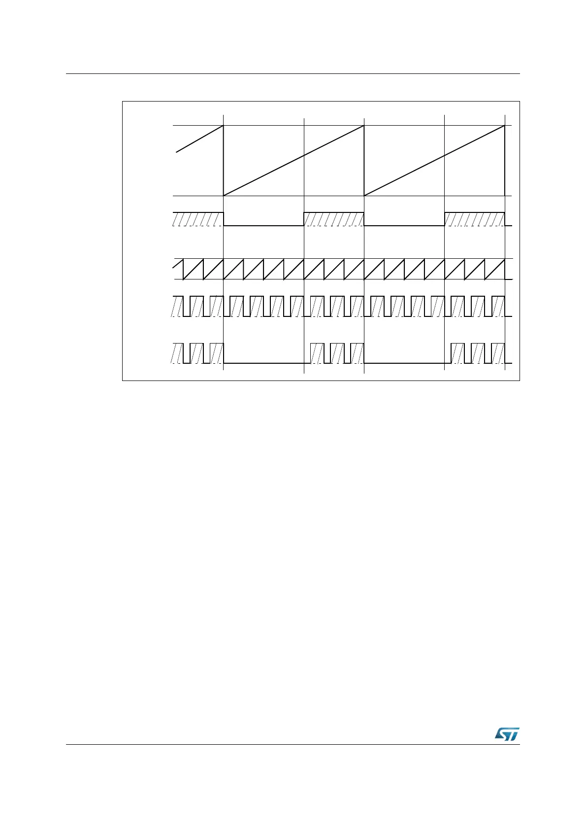
Figure 148. Operation and output waveform in burst mode
17.1.4 Single shot mode
Single shot mode is selected by setting the respective bit PSx in register PWMCON1 to ‘1’.
This mode is available for PWM channels 2 and 3.
In this mode the timer PTx of the respective PWM channel is started via software and is
counting up until it reaches the value in the associated period shadow register. Upon the
next count pulse the timer is cleared to 0000h and stopped via hardware, (the respective
PTRx bit is cleared). The PWM output signal is switched to high level when the timer
contents are equal to or greater than the contents of the pulse width shadow register. The
signal is switched back to low level when the respective timer is cleared, because it is below
the pulse width shadow register.
Thus starting a PWM timer in single shot mode produces one single pulse on the respective
port pin, provided that the pulse width value is between 0000h and the period value. In order
to generate a further pulse, the timer has to be started again via software by setting bit PTRx
(see Figure 149).
PP0
Period
Value
PT0
Count
Value
Channel 0
PP1
PT1
Channel 1
Resulting
Output
POUT0