XBUS pulse width modulation module UM0404
364/564 DocID13284 Rev 2
Up/down counters XPTx
Each counter XPTx of a XPWM channel is clocked either directly by the CPU clock or by the
CPU clock divided by 64. Bit PTIx in register XPWMCON0 selects the respective clock
source. A XPWM counter counts up or down (controlled by hardware), while its respective
run control bit PTRx is set. A timer is started (PTRx = ‘1’) via software and is stopped
(PTRx = ‘0’) either via hardware or software, depending on its operating mode. Control bit
PTRx enables or disables the clock input of counter XPTx rather than controlling the PWM
output signal.
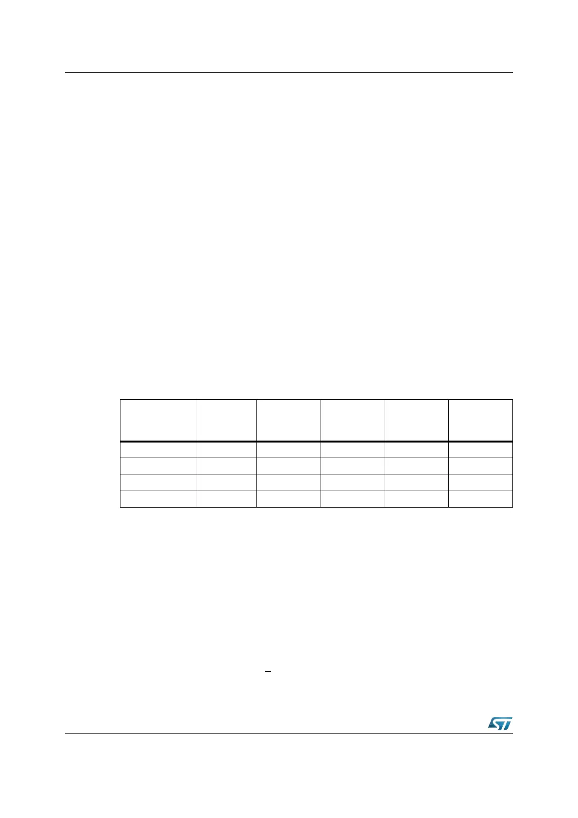
Table 52 summarizes the XPWM frequencies that result from various combinations of
operating mode, counter resolution (input clock) and pulse width resolution.
Period registers XPPx
The 16-bit period register XPPx of a XPWM channel determines the period of a PWM cycle
and the frequency of the PWM signal. This register is buffered with a shadow register.
The shadow register is loaded from the respective XPPx register at the beginning of every
new PWM cycle, or upon a write access to XPPx, while the timer is stopped. The CPU
accesses the XPPx register while the hardware compares the contents of the shadow
register with the contents of the associated counter XPTx.
When a match is found between counter and XPPx shadow register, the counter is either
reset to 0000h, or the count direction is switched from counting up to counting down,
depending on the selected operating mode of that XPWM channel. For the register locations
refer to Table 53.
Pulse width registers XPWx
This 16-bit register holds the actual PWM pulse width value which corresponds to the duty
cycle of the PWM signal. This register is buffered with a shadow register.
The CPU accesses the XPWx register while the hardware compares the contents of the
shadow register with the contents of the associated counter XPTx. The shadow register is
loaded from the respective XPWx register at the beginning of every new PWM cycle, or
upon a write access to XPWx, while the timer is stopped.
When the counter value is greater than or equal to the shadow register value, the PWM
signal is set, otherwise it is reset. The output of the comparators may be described by the
boolean formula:
PWM output signal = [XPTx] >
[XPWx shadow latch]
Table 54. XPWM frequencies
Input Clock and
Mode (Counter
resolution)
8-bit PWM
resolution
10-bit PWM
resolution
12-bit PWM
resolution
14-bit PWM
resolution
16-bit PWM
resolution
f
CPU
Mode 0 f
CPU
/ 2
8
f
CPU
/ 2
10
f
CPU
/ 2
12
f
CPU
/ 2
14
f
CPU
/ 2
16
f
CPU
/ 64Mode 0 f
CPU
/ 64x2
8
f
CPU
/ 64x2
10
f
CPU
/ 64x2
12
f
CPU
/ 64x2
14
f
CPU
/ 64x2
16
f
CPU
Mode 1 f
CPU
/ 2x2
8
f
CPU
/ 2x2
10
f
CPU
/ 2x2
12
f
CPU
/ 2x2
14
f
CPU
/ 2x2
16
f
CPU
/ 64Mode 1 f
CPU
/ 2x64x2
8
f
CPU
/ 2x64x2
10
f
CPU
/ 2x64x2
12
f
CPU
/ 2x64x2
14
f
CPU
/ 2x64x2
16