The general purpose timer units UM0404
230/564 DocID13284 Rev 2
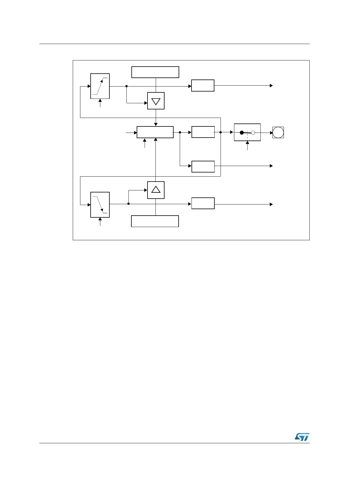
Figure 87. GPT1 timer reload configuration for PWM generation
Note: Lines only affected by over/underflows of T3, but NOT by software modifications of T3OTL.
Auxiliary timer in capture mode
Capture mode for the auxiliary timers T2 and T4 is selected by setting bit-field TxM in the
respective register TxCON to ‘101b’.
In capture mode the contents of the core timer are latched into an auxiliary timer register in
response to a signal transition at the respective auxiliary timer's external input pin TxIN.
The capture trigger signal can be a positive, a negative, or both a positive and a negative
transition.
The two least significant bit of bit-field TxI are used to select the active transition (see table
in the counter mode section), while the most significant bit TxI.2 is irrelevant for capture
mode. It is recommended to keep this bit cleared (TxI.2 = ‘0’).
Note: When programmed for capture mode, the respective auxiliary timer (T2 or T4) stops
independent of its run flag T2R or T4R.
T2l
T4l
Reload Register T2
T2IR
Interrupt
Core Timer T3
Up/Down
Input
Clock
T3OTL
Interrupt
T3IR
T3OE
T3OUT
P3.3
Reload Register T4
T4IR
Interrupt
1)
1)
Request
Request
Request