DocID13284 Rev 2 395/564
UM0404 I
2
C interface
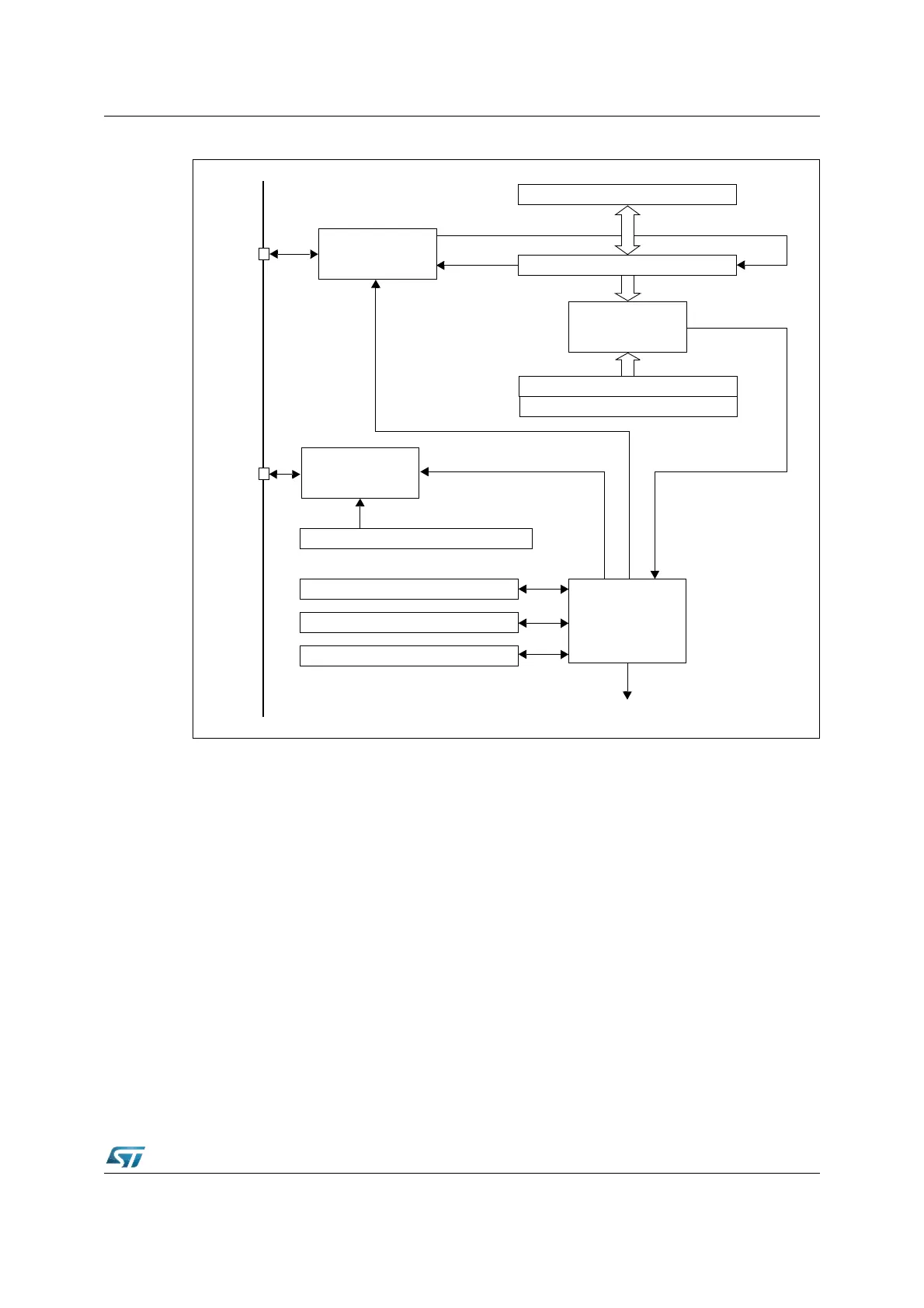
Figure 169. I
2
C interface block diagram
20.3 Functional description
Refer to the I2CCR, I2CSR1 and I2CSR2 registers in Section 20.5: Register description for
the bit definitions.
By default the I
2
C interface operates in Slave mode (M/SL bit is cleared) except when it
initiates a transmit or receive sequence.
First the interface frequency must be configured using the FRx bits in the I2COAR2 register.
20.3.1 Slave mode
As soon as a start condition is detected, the address is received from the SDA line and sent
to the shift register; then it is compared with the address of the interface or the General Call
address (if selected by software).
Note: In 10-bit addressing mode, the comparison includes the header sequence (11110xx0) and
the two most significant bits of the address.
DATA REGISTER (I2CDR)
DATA SHIFT REGISTER
COMPARATOR
OWN ADDRESS REGISTER 1 (I2COAR1)
CLOCK CONTROL REGISTER (I2CCCR1/2)
STATUS REGISTER 1 (I2CSR1)
CONTROL REGISTER (I2CCR)
CONTROL LOGIC
STATUS REGISTER 2 (I2CSR2)
INTERRUPT
CLOCK CONTROL
DATA CONTROL
SCL
SDA
OWN ADDRESS REGISTER 2 (I2COAR2)