System reset UM0404
472/564 DocID13284 Rev 2
23 System reset
System reset initializes the device in a predefined state. There are many ways to activate a
reset state. The system start-up configuration is different for each case as shown in
Table 63. The reset history is flagged inside WDTCON register (see also Section 14:
Watchdog timer on page 297 for additional details).
23.1 Input filter
On RSTIN input pin an on-chip RC filter is implemented. It is sized to filter all the spikes
shorter than 50ns. On the other side, a valid pulse should be longer than 500ns to grant that
ST10 recognizes a reset command. In between 50ns and 500ns a pulse can either be
filtered or recognized as valid, depending on the operating conditions and process
variations.
For this reason all minimum durations mentioned in this section for the different kind of reset
events should be carefully evaluated taking into account of the above requirements.
In particular, for Short Hardware Reset, where only 4 TCL is specified as minimum input
reset pulse duration, the operating frequency is a key factor. Examples:
• for a CPU clock of 64 MHz, 4 TCL is 31.25ns, so it would be filtered: in this case the
minimum becomes the one imposed by the filter (that is 500ns).
• for a CPU clock of 4 MHz, 4 TCL is 500ns: in this case the minimum from the formula is
coherent with the limit imposed by the filter.
23.2 Asynchronous reset
An asynchronous reset is triggered when RSTIN pin is pulled low while RPD pin is at low
level. Then the ST10F276 is immediately (after the input filter delay) forced in reset default
state. It pulls low RSTOUT
pin, it cancels pending internal hold states if any, it aborts all
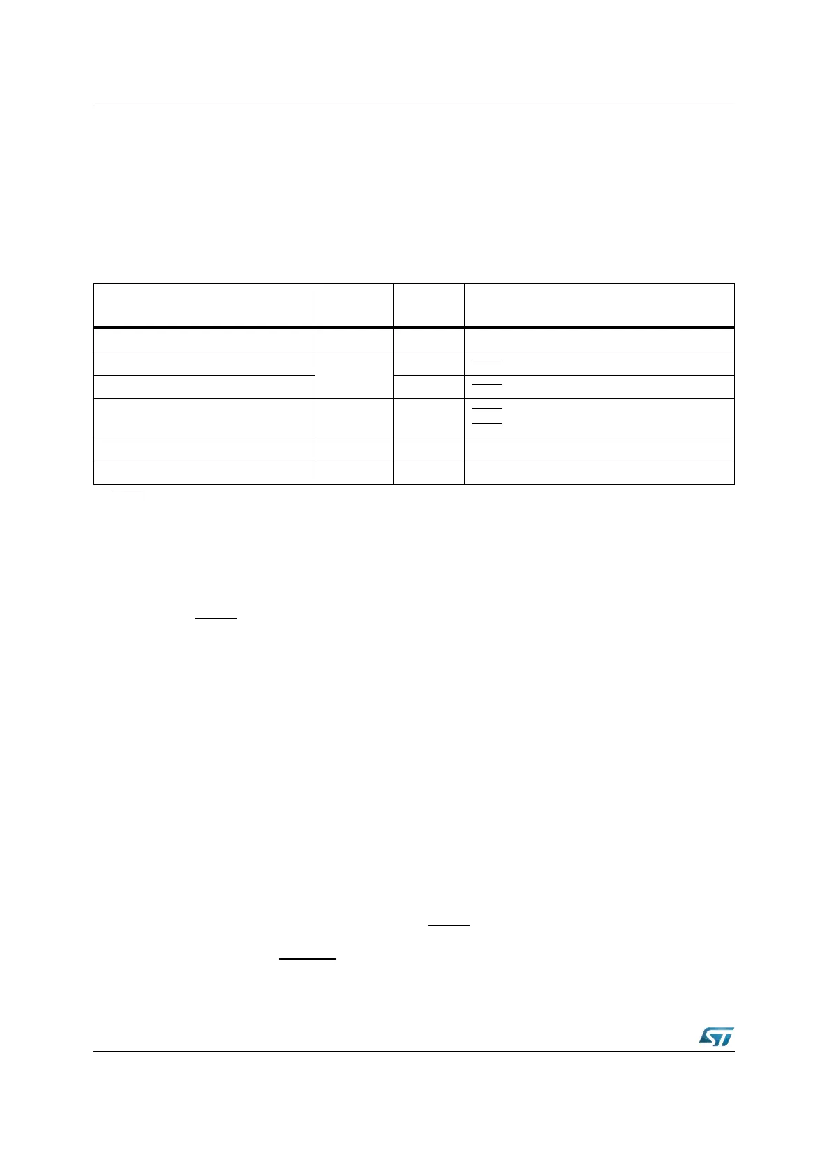
Table 63. Reset event definition
Reset source Flag
RPD
status
Conditions
Power-On reset PONR Low Power-On
Asynchronous Hardware reset
LHWR
Low t
RSTIN
>
(1)
Synchronous Long Hardware reset High t
RSTIN
> (1032 + 12) TCL + max(4 TCL, 500ns)
Synchronous Short Hardware reset SHWR High
t
RSTIN
> max(4 TCL, 500ns)
t
RSTIN
≤ (1032 + 12) TCL + max(4 TCL, 500ns)
Watchdog Timer reset WDTR
(2)
WDT overflow
Software reset SWR note
(2)
SRST instruction execution
1. RSTIN pulse should be longer than 500ns (Filter) and than settling time for configuration of Port0. See next Section 24.1 for
more details on minimum reset pulse duration.
2. The RPD status has no influence unless Bidirectional Reset is activated (bit BDRSTEN in SYSCON): RPD low inhibits the
Bidirectional reset on SW and WDT reset events, that is RSTIN is not activated (refer to Section 23.4: Software reset,
Section 23.5: Watchdog timer reset and Section 23.6: Bidirectional reset).