DocID13284 Rev 2 369/564
UM0404 XBUS pulse width modulation module
either to initialize the system or to react on some extraordinary condition, like a system fault
or an emergency.
Clearing the timer run bit PTRx stops the associated counter and leaves the respective
output at its current level.
The individual XPWM channel outputs are controlled by comparators according to the
formula:
PWM output signal = [XPTx] >
[XPWx shadow latch]
So whenever software changes registers XPTx, the respective output will reflect the
condition after the change. Loading timer XPTx with a value greater than or equal to the
value in XPWx immediately sets the respective output, a XPTx value below the XPWx value
clears the respective output.
By clearing or setting the respective Port8 output latch the XPWM channel signal is driven
directly or inverted to the port pin.
Clearing the enable bit PENx disconnects the XPWM channel and switches the respective
port pin to the value in the port output latch.
Note: To prevent further PWM pulses from occurring after such a software intervention the
respective counter must be stopped first.
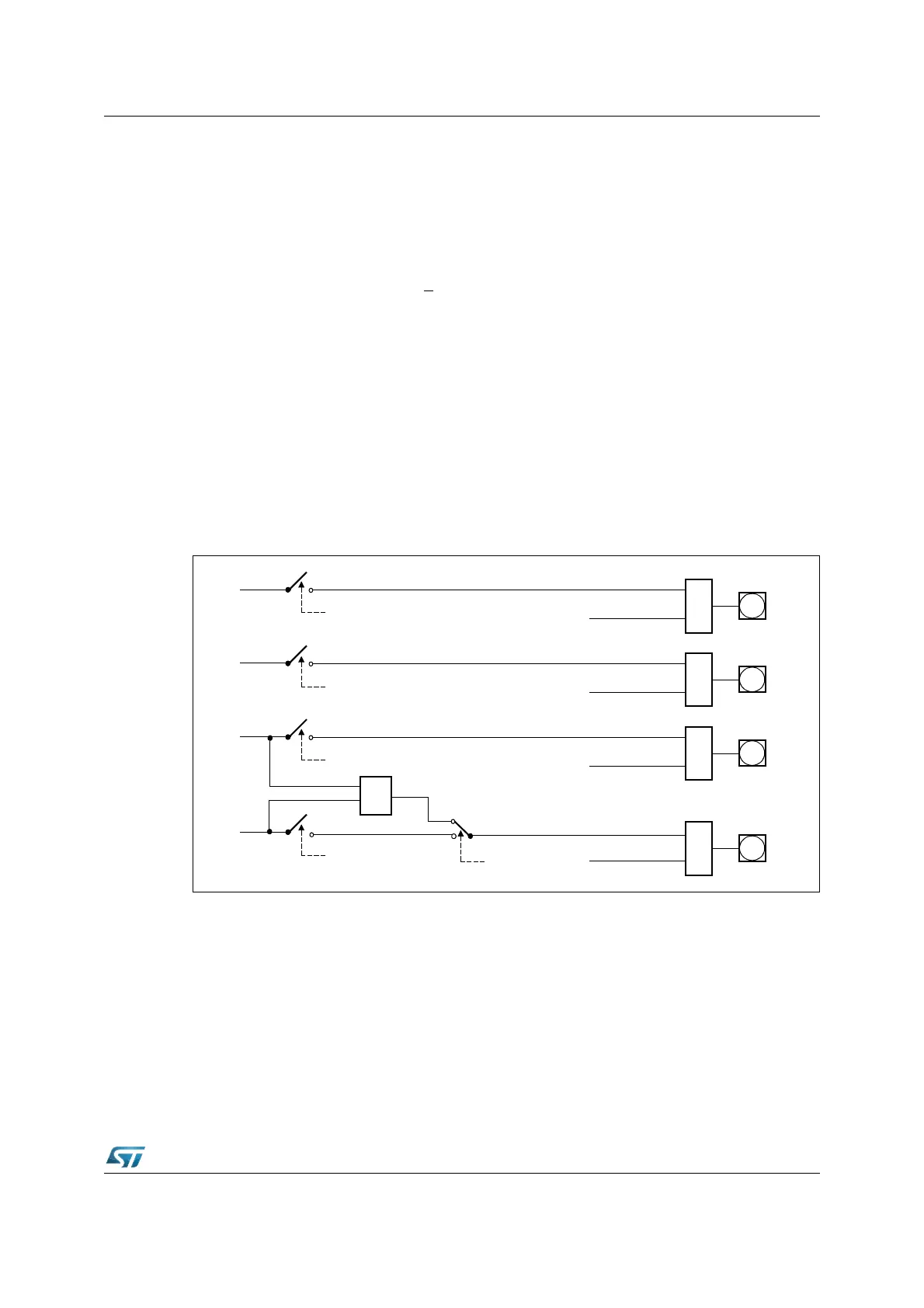
Figure 157. XPWM output signal generation
Latch XPOLAR.3
XPWM 3
Pin P8.3
Latch XPOLAR.2
XPWM 2
Pin P8.2
Latch XPOLAR.1
XPWM 1
Pin P8.1
Latch XPOLAR.0
XPWM 0
Pin P8.0
XORXORXORXOR
&
XPWMCON1.PEN3
XPWMCON1.PEN2
XPWMCON1.PEN0
XPWMCON1.PEN1
XPWMCON1.PB01