The bootstrap loader UM0404
308/564 DocID13284 Rev 2
Note: As long as ST10F276 is in BSL, user’s software should not try to execute code from the
internal IFlash as the fetches are redirected to the Test-Flash.
15.2.6 Loading the start-up code
After the serial link initialization sequence (see following sections), the BSL enters a loop to
receive 32bytes (boot via UART) or 128bytes (boot via CAN).
These bytes are stored sequentially into ST10F276 Dual-Port RAM from location 00’FA40h.
To execute the loaded code, the BSL then jumps to location 00’FA40h. The bootstrap
sequence running from the Test-Flash is now terminated; the microcontroller remains in BSL
mode however.
Most probably, the initially loaded routine, the first level user code, will load additional code
and data. This first level user code may use the pre-initialized interface (UART or CAN) to
receive data, a second level of code, and store it to arbitrary user-defined locations.
This second level of code may be the final application code. It may also be another, more
sophisticated, loader routine that adds a transmission protocol to enhance the integrity of
the loaded code or data. It may also contain a code sequence to change the system
configuration and enable the bus interface to store the received data into external memory.
In all cases, the ST10F276 will still run in BSL mode, that is, with the watchdog timer
disabled and limited access to the internal IFLASH area.
15.2.7 Exiting bootstrap loader mode
In order to execute a program in normal mode, the BSL mode must be terminated first. The
ST10F276 exits BSL mode upon a software reset (level on P0L.4 is ignored) or a hardware
reset (P0L.4 must be high in this case). After the reset, the ST10F276 will start executing
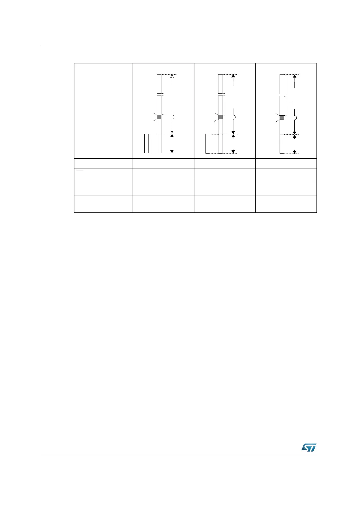
Figure 127. Memory configuration after reset
16 Mbytes
16 Mbytes
16 Mbytes
BSL mode active Yes (P0L.4 = ‘0’) Yes (P0L.4 = ‘0’) No (P0L.4 = ‘1’)
EA
pin high low according to application
Code fetch from
internal FLASH area
Test-FLASH access Test-FLASH access User IFLASH access
Data fetch from
internal FLASH area
User IFLASH access User IFLASH access User IFLASH access
int. Flash
enabled
Test-Flash
user FLASH
access to
external
bus
disabled
access to
int.
RAM
1
0
255
int. Flash
enabled
Test-Flash
user FLASH
access to
external
bus
enabled
access to
int.
RAM
1
0
255
Depends on
reset config.
user FLASH
int.
RAM
255
1
0
Depends on
reset config.
(EA, P0)