DocID13284 Rev 2 297/564
UM0404 Watchdog timer
14 Watchdog timer
The watchdog timer (WDT) provides recovery from software or hardware failure. If the
software fails to service this timer before an overflow occurs, an internal reset sequence is
initiated.
This internal reset will also pull the RSTOUT
pin low, this resets the peripheral hardware
which might have caused the malfunction. When the watchdog timer is enabled and is
serviced regularly to prevent overflows, the watchdog timer supervises program execution.
Overflow only occurs if the program does not progress properly.
The watchdog timer will time out, if a software error was due to hardware related failures.
This prevents the controller from malfunctioning for longer than a user-specified time.
The watchdog timer provides two registers:
• Read-only timer register that contains the current count.
• Control register for initialization.
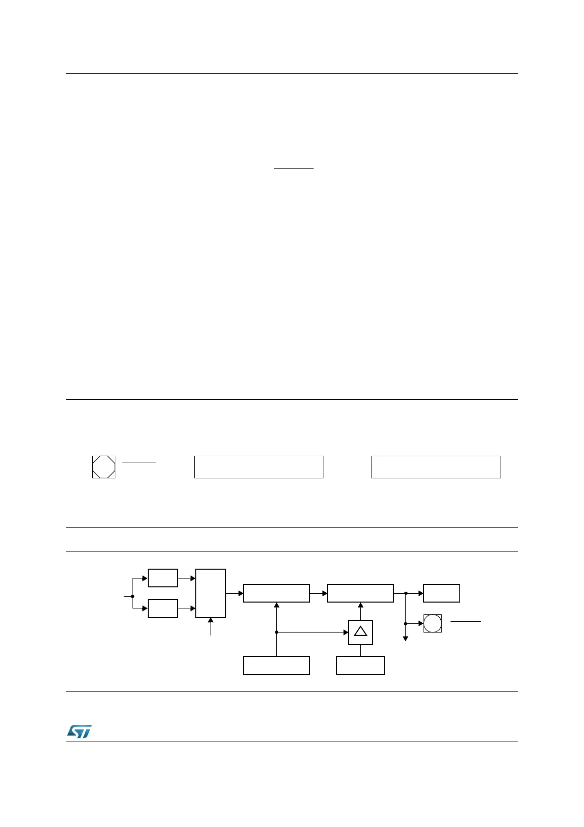
The watchdog timer is a 16-bit up counter which can be clocked with the CPU clock (f
CPU
)
either divided by 2 or divided by 128. This 16-bit timer is realized as two concatenated 8-bit
timers (see Figure 123).
The upper 8 bits of the watchdog timer can be preset to a user-programmable value by a
watchdog service access, in order to program the watchdog expire time. The lower 8 bits
are reset on each service access.
Figure 122. SFRs and port pins associated with the watchdog timer
Figure 123. Watchdog timer block diagram
Data Registers Control Registers
15
Y
14
Y
13
Y
12
Y
11
Y
10
Y
9
Y
8
Y
7
Y
6
Y
5
Y
4
Y
3
Y
2
Y
1
Y
0
Y
WDT
15 14 13 12 11 10 9 8 7 6 5 4 3 2 1 0
WDTCON YYYYY Y YY- - YYYYYY
Reset Indication Pin
RSTOUT
Bit is linked to a function
Bit has no function or is not implemented
Register is in ESFR internal memory space
Y
-
E
:
:
:
÷
2
÷
128
MUX
WDTIN
WDT Low Byte WDT High Byte WDTR
Reset
WDTREL
Clear
WDT Control
f
CPU
RSTOUT