XBUS high-speed synchronous serial interface UM0404
286/564 DocID13284 Rev 2
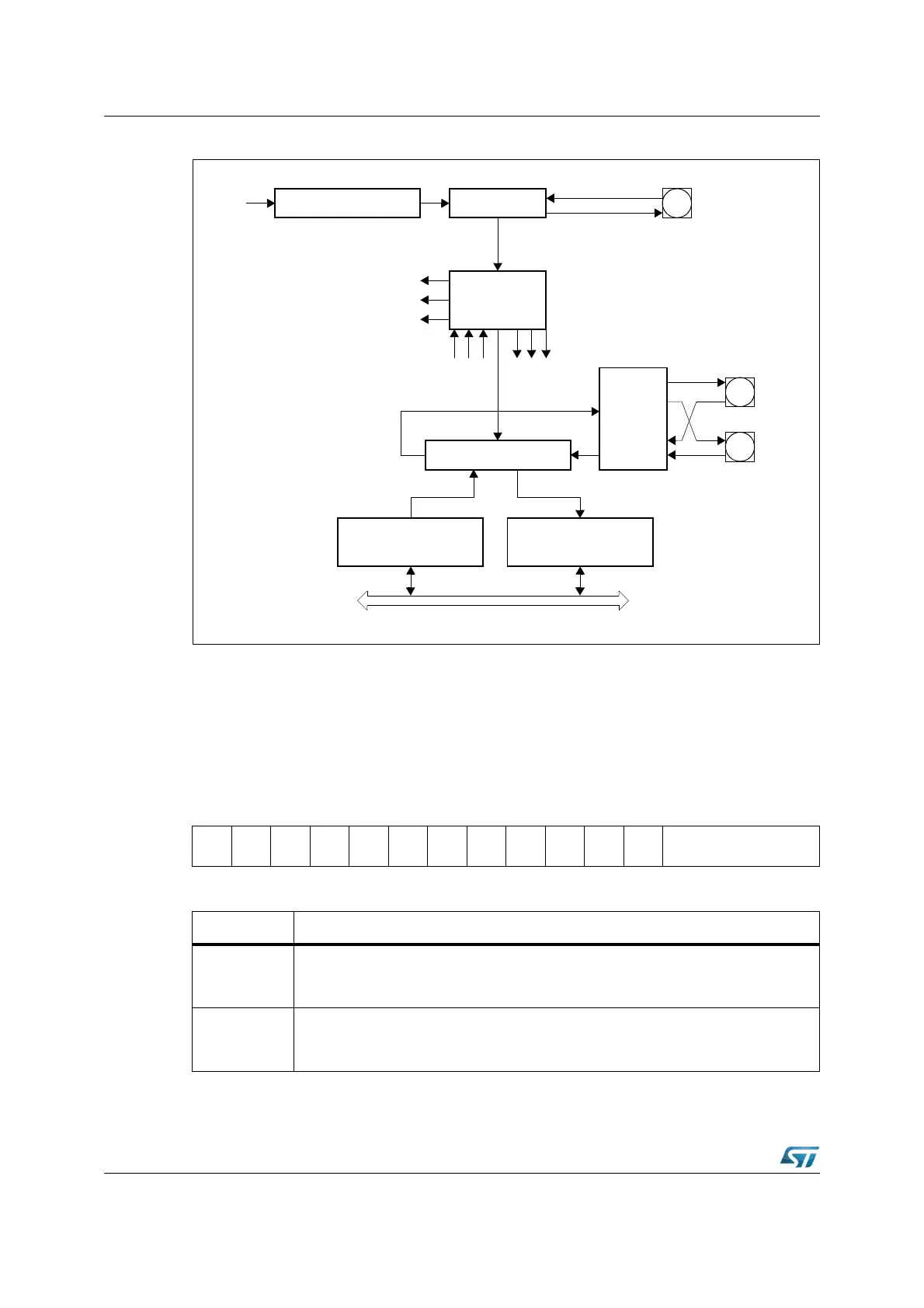
Figure 118. Synchronous serial channel XSSC block diagram
The operating mode of the serial channel XSSC is controlled by its bit-addressable control
register XSSCCON. This register serves for two purposes:
• During programming (XSSC disabled by SSCEN = ‘0’) it provides access to a set of
control bits.
• During operation (XSSC enabled by SSCEN = ‘1’) it provides access to a set of status
flags. Register XSSCCON is shown below in each of the two modes.
XSSCCON (E800h) XBUS Reset Value: 0000h
1514131211109876543210
SSC
EN=0
SSC
MS
-
SSC
AREN
SSC
BEN
SSC
PEN
SSC
REN
SSC
TEN
-
SSC
PO
SSC
PH
SSC
HB
SSCBM
RW RW RW RW RW RW RW RW RW RW RW
Bit Function (programming mode, SSCEN = ‘0’)
SSCBM
XSSC Data Width Selection
0: Reserved. Do not use this combination.
1...15: Transfer Data Width is 2...16-bit [(SSCBM)+1]
SSCHB
XSSC Heading Control bit
0: Transmit/Receive LSB First
1: Transmit/Receive MSB First
Baud Rate Generator
XSSC Control
Block
Internal X-Bus
Clock Control
CPU
Clock
Slave Clock
Master Clock
SCLK1
Shift
Clock
Status Control
Receive Interrupt Request
Transmit Interrupt Request
Error Interrupt Request
16-bit Shift Register
Pin
Control
MTSR1
MRST1
Transmit Buffer
Register XSSCTB
Receive Buffer
Register XSSCRB
P6.5
P6.6
P6.7