DocID13284 Rev 2 287/564
UM0404 XBUS high-speed synchronous serial interface
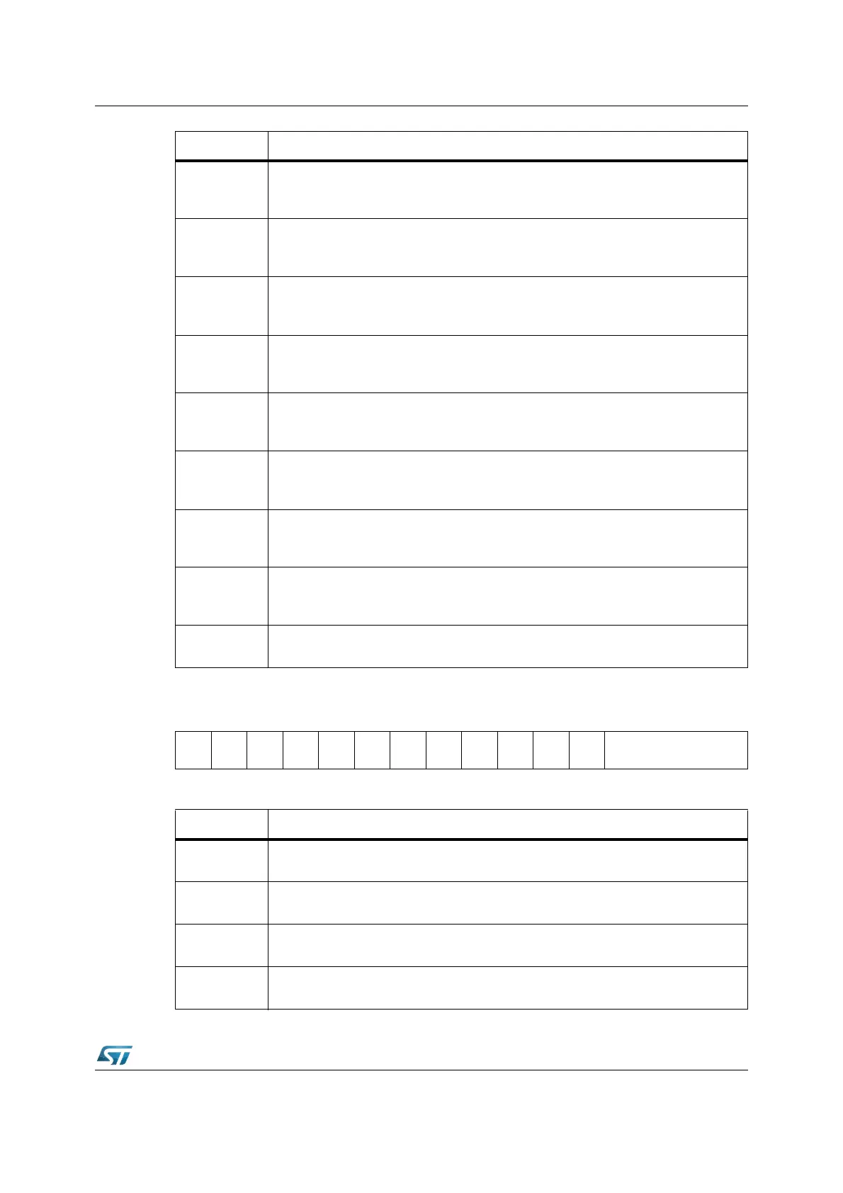
XSSCCON (E800h) XBUS Reset Value: 0000h
SSCPH
XSSC Clock Phase Control bit
0: Shift transmit data on the leading clock edge, latch on trailing edge
1: Latch receive data on leading clock edge, shift on trailing edge
SSCPO
XSSC Clock Polarity Control bit
0: Idle clock line is low, leading clock edge is low-to-high transition
1: Idle clock line is high, leading clock edge is high-to-low transition
SSCTEN
XSSC Transmit Error Enable bit
0: Ignore transmit errors
1: Check transmit errors
SSCREN
XSSC Receive Error Enable bit
0: Ignore receive errors
1: Check receive errors
SSCPEN
XSSC Phase Error Enable bit
0: Ignore phase errors
1: Check phase errors
SSCBEN
XSSC Baudrate Error Enable bit
0: Ignore baudrate errors
1: Check baudrate errors
SSCAREN
XSSC Automatic Reset Enable bit
0: No additional action upon a baudrate error
1: The XSSC is automatically reset upon a baudrate error
SSCMS
XSSC Master Select bit
0: Slave Mode. Operate on shift clock received via SCLK1.
1: Master Mode. Generate shift clock and output it via SCLK1.
SSCEN
XSSC Enable bit = ‘0’
Transmission and reception disabled. Access to control bits.
1514131211109876543210
SSC
EN=1
SSC
MS
-
SSC
BSY
SSC
BE
SSC
PE
SSC
RE
SSC
TE
---- SSCBC
RW RW RW RW RW RW RW RW
Bit Function (operating mode, SSCEN = ‘1’)
SSCBC
XSSC bit Count Field
Shift counter is updated with every shifted bit. Do not write to
SSCTE
XSSC Transmit Error Flag
1: Transfer starts with the slave’s transmit buffer not being updated
SSCRE
XSSC Receive Error Flag
1: Reception completed before the receive buffer was read
SSCPE
XSSC Phase Error Flag
1: Received data changes around sampling clock edge
Bit Function (programming mode, SSCEN = ‘0’)