XBUS high-speed synchronous serial interface UM0404
288/564 DocID13284 Rev 2
Note: The target of an access to XSSCCON (control bits or flags) is determined by the state of
SSCEN prior to the access. Writing C057h to XSSCCON in programming mode
(SSCEN = ‘0’) will initialize the XSSC (SSCEN was ‘0’) and then turn it on (SSCEN = ‘1’).
When writing to XSSCCON, make sure that reserved locations receive zeros.
All XSSCCON bits can be individually (bit-wise) programmed. The “bit-addressable” feature
is available via specific “Set” and “Clear” registers: XSSCCONSET, XSSCCONCLR.
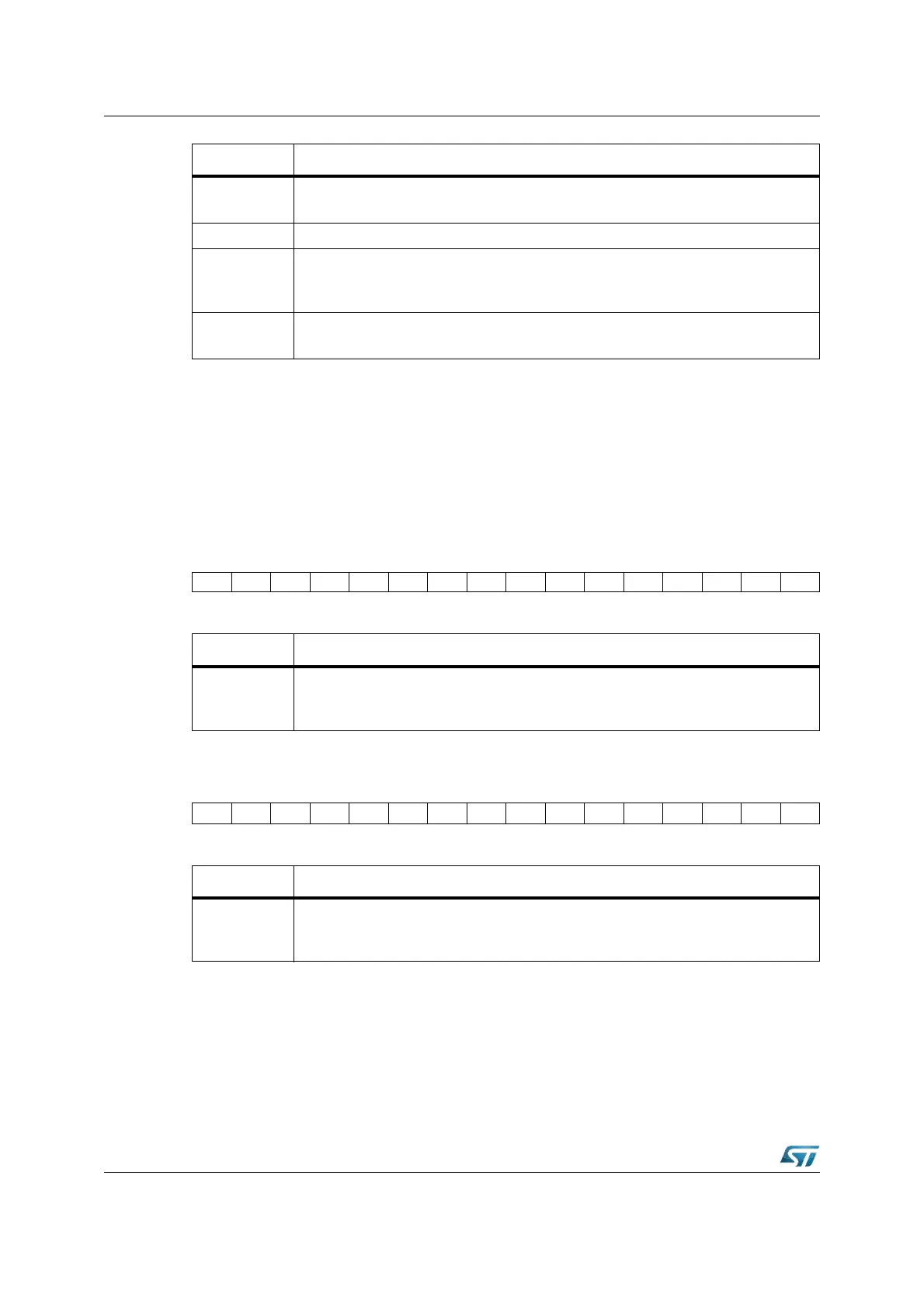
XSSCCONSET (E802h) XBUS Reset Value: 0000h
XSSCCONCLR (E804h) XBUS Reset Value: 0000h
The shift register of the XSSC is connected to both the transmit pin and the receive pin via
the pin control logic (see Figure 118). Transmission and reception of serial data is
synchronized and takes place at the same time, so the same number of transmitted bit is
also received. Transmit data is written into the Transmit Buffer XSSCTB.
SSCBE
XSSC Baud rate Error Flag
1: More than factor 2 or 0.5 between Slave’s actual and expected Baud rate
SSCBSY XSSC Busy Flag: Set while a transfer is in progress. Do not write to
SSCMS
XSSC Master Select bit
0: Slave Mode. Operate on shift clock received via SCLK1.
1: Master Mode. Generate shift clock and output it via SCLK1.
SSCEN
XSSC Enable bit = ‘1’
Transmission and reception enabled. Access to status flags and M/S control.
Bit Function (operating mode, SSCEN = ‘1’)
15 14 13 12 11 10 9 8 7 6 5 4 3 2 1 0
SET.15 SET.14 - SET.12 SET.11 SET.10 SET.9 SET.8 - SET.6 SET.5 SET.4 SET.3 SET.2 SET.1 SET.0
WW WWWWW WWWWWWW
Bit Function
SET.Y
XSSCCON Bit Y Set
Writing a ‘1’ will set the corresponding bit in XSSCCON register.
Writing a ‘0’ has no effect.
15 14 13 12 11 10 9 8 7 6 5 4 3 2 1 0
CLR.15 CLR.14 - CLR.12 CLR.11 CLR.10 CLR.9 CLR.8 - CLR.6 CLR.5 CLR.4 CLR.3 CLR.2 CLR.1 CLR.0
WW WWWWW WWWWWWW
Bit Function
SET.Y
XSSCCON Bit Y Clear
Writing a ‘1’ will clear the corresponding bit in XSSCCON register.
Writing a ‘0’ has no effect.