Interrupt and trap functions UM0404
112/564 DocID13284 Rev 2
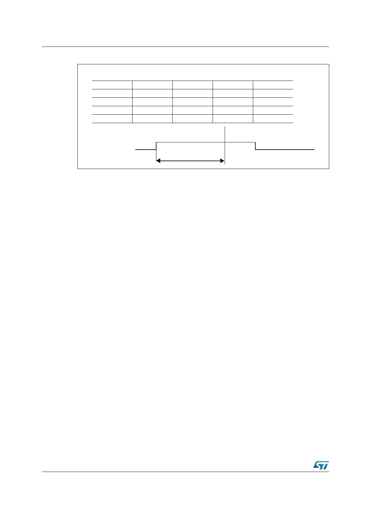
Figure 23. Pipeline diagram for PEC response time
In Figure 23 the respective interrupt request flag is set in cycle 1 (fetching of instruction N).
The indicated source wins the prioritization round (during cycle 2). In cycle 3 a PEC transfer
“instruction” is injected into the decode stage of the pipeline, suspending instruction N+1
and clearing the source's interrupt request flag to '0'. Cycle 4 completes the injected PEC
transfer and resumes the execution of instruction N+1. All instructions that entered the
pipeline after setting of the interrupt request flag (N+1, N+2) will be executed after the PEC
data transfer.
Note: When instruction N reads any of the PEC control registers PECC7...PECC0, while a PEC
request wins the current round of prioritization, this round is repeated and the PEC data
transfer is started one cycle later.
The minimum PEC response time is three CPU clock cycles. This requires program
execution from the internal Flash, no external operand read requests and setting the
interrupt request flag during the last CPU clock cycle of an instruction. When the interrupt
request flag is set during the first CPU clock cycle of an instruction, the minimum PEC
response time is four CPU clock cycles. The PEC response time is increased by all delays
of the instructions in the pipeline that are executed before starting the data transfer
(including N):
• When internal hold conditions between instruction pairs N-2/N-1 or N-1/N occur, the
minimum PEC response time may be extended by 1 CPU clock cycle for each of these
conditions.
• When instruction N reads an operand from the internal Flash, or when N is a CALL,
RETURN, TRAP, or MOV Rn, [Rm+ #data16] instruction, the minimum PEC response
time may additionally be extended by two CPU clock cycles during internal Flash
program execution.
• In case instruction N reads the PSW and instruction N-1 has an effect on the condition
flags, the PEC response time may additionally be extended by two CPU clock cycles.
The worst case PEC response time during internal Flash program execution adds to nine
CPU clock cycles. Any reference to external locations increases the PEC response time due
to pipeline related access priorities. The following conditions have to be considered:
• Instruction fetch from an external location
• Operand read from an external location
• Result write-back to an external location
Pipeline Stage Cycle 1 Cycle 2 Cycle 3 Cycle 4
FETCH N N + 1 N + 2 N + 2
DECODE N - 1 NPECN + 1
EXECUTE N - 2 N - 1 N PEC
WRITEBACK N - 3 N - 2 N - 1 N
PEC Response Time
1
0
IR-Flag