Architectural overview UM0404
30/564 DocID13284 Rev 2
The on-chip XRAM and XFlash, the on-chip CAN-Modules, the XASC, the XSSC, the
XPWM, the I
2
C interface, the RTC are all examples for these X-Peripherals.
1.3 Clock generator
The on-chip clock generator provides the ST10F276 with its basic clock signal that controls
the activities of the controller hardware. Its oscillator amplifier can run with an external
crystal and appropriate oscillator circuitry (see Section 7: Dedicated pins on page 179), or
can be driven by an external clock source.
Direct Drive mode allows to feed the device with an external clock signal to provide directly
the clock to the CPU, up to maximum internally allowed speed. In this mode, the on-chip
oscillator amplifier is bypassed, so there is no limit imposed by the bandwidth of the
amplifier circuit itself.
On the contrary, for all the other configurations, the on-chip oscillator amplifier is not
bypassed, so the external clock can be provided by a crystal or resonator only, according to
the limited frequency ranges (refer to datasheet for more details).
The resulting internal clock signal is also referred to as “CPU clock”. Two separated clock
signals are generated for the CPU itself and the peripheral part of the chip.
While the CPU clock is stopped during idle mode, the peripheral clock keeps running. Both
clocks are switched off when the Power Down mode is entered.
The on-chip PLL circuit allows operation of the ST10F276 with a low frequency external
clock while still providing maximum performance.
The PLL multiplies the external clock frequency by a selectable factor F (0.5, 1, 3, 4, 5, 8,
10, 16) and generates a CPU clock signal with 50% duty cycle.
The PLL also provides fail safe mechanisms which allows the detection of frequency
deviations and the execution of emergency actions in case of an external clock failure even
when PLL is bypassed (see Section 1.3.4: Oscillator watchdog (OWD) on page 32).
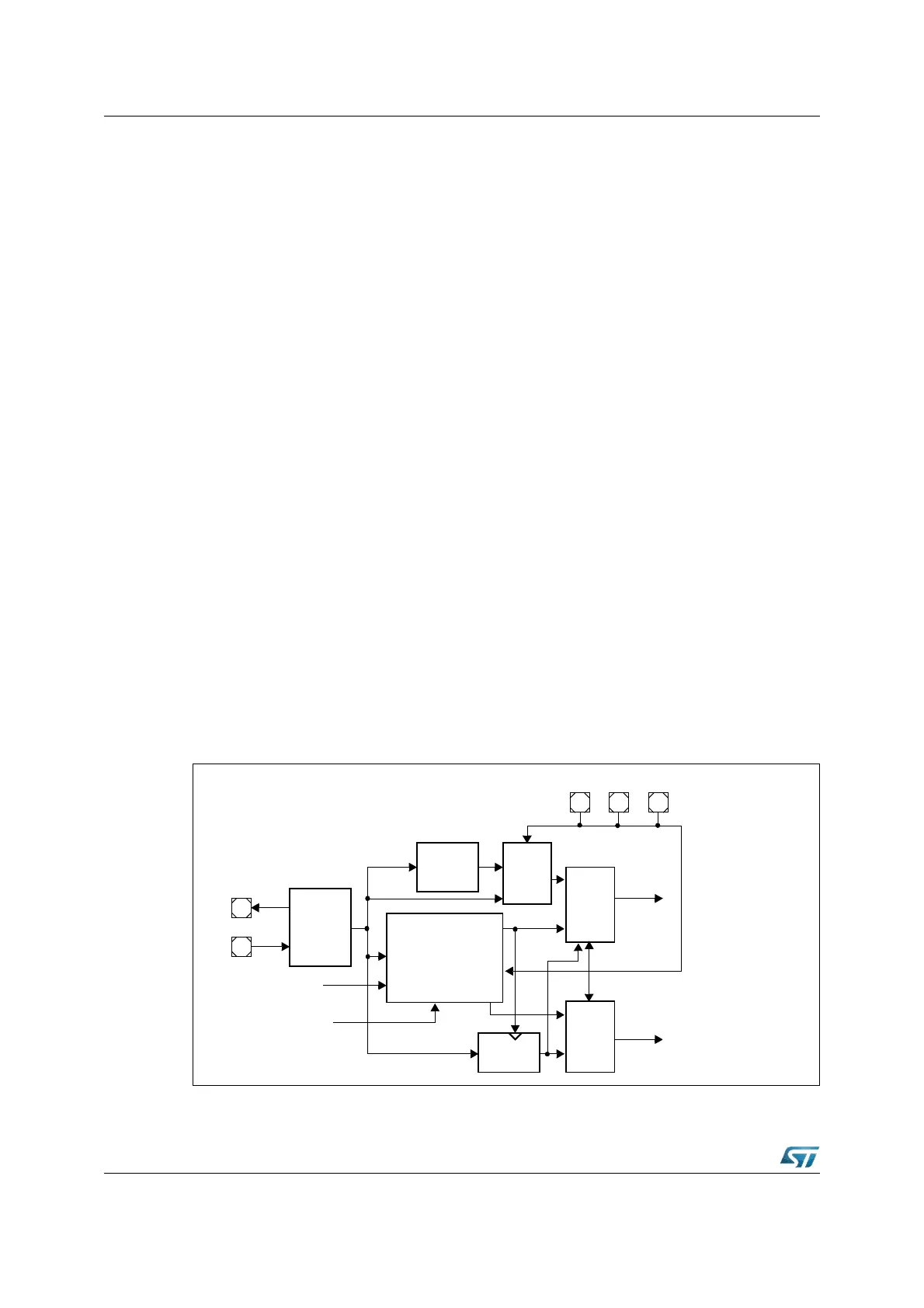
Figure 3. Clock block diagram
MUX
Oscillator
Circuit
Reset
PWRDN
XBUS interrupt
f
PLL
f
XTAL
f
CPU
XTAL2
XTAL1
Oscillator
Watchdog
Prescaler
(÷ 2)
MUX
P0H.7
MUX
P0H.6 P0H.5
PLL Circuit
f
PLL
= F x f
IN
reset sleep
Unlock
Factor