DocID13284 Rev 2 331/564
UM0404 The capture / compare units
Note: This selection is available for timers T0 and T7. Timers T1 and T8 will stop at this selection!
The run flags T0R, T1R, T7R and T8R enable or disable the timers. The following
description of the timer modes and operation always applies to the enabled state of the
timers, the respective run flag is assumed to be set to '1'.
In all modes, the timers are always counting upward. The current timer values are
accessible for the CPU in the timer registers Tx, which are non bit-addressable SFRs. When
the CPU writes to a register Tx in the state immediately before the respective timer
increment, a reload is to be performed, the CPU write operation has priority and the
increment or reload is disabled to guarantee correct timer operation.
Timer mode
The bit TxM in SFRs T01CON and T78CON selects the timer mode or the counter mode. In
timer mode (TxM = ‘0’), the input clock of a timer is derived from the internal CPU clock
divided by a programmable pre-scaler.
The different options of the pre-scaler of each timer are selected separately by the bit-fields
TxI.
The input frequencies f
Tx
for Tx are determined as a function of the CPU clock as follows,
where (TxI) represents the contents of the bit-field TxI:
When a timer overflows from FFFFh to 0000h it is reloaded with the value stored in its
respective reload register TxREL.
The reload value determines the period P
Tx
between two consecutive overflows of Tx as
follows:
The timer resolutions against pre-scaler option in TxI are listed in the table below.
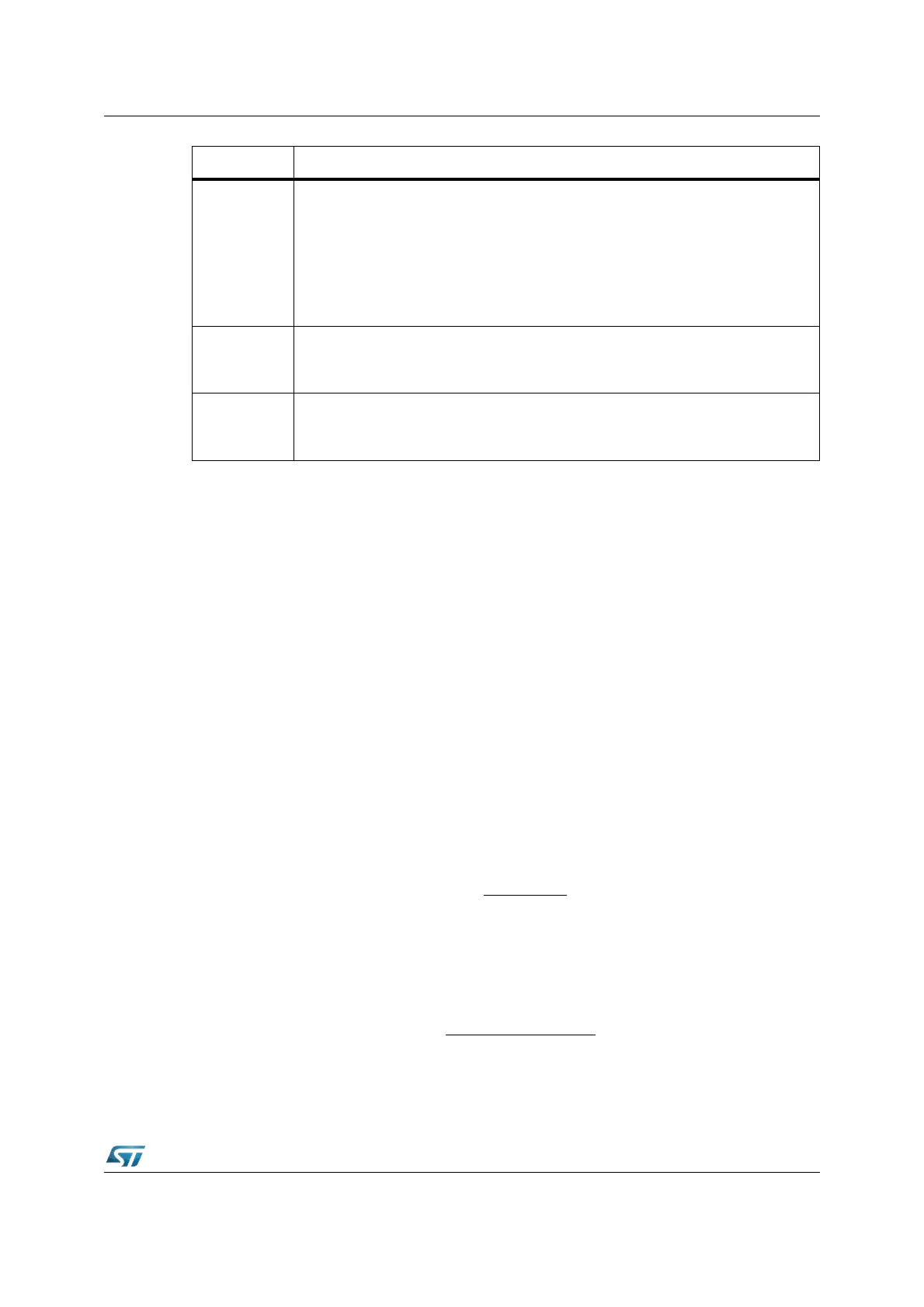
Bit Function
TxI
Timer / Counter x Input Selection
Timer Mode (TxM
= ‘0’) Input Frequency = f
CPU
/ 2
[(TxI)+3]
See also table below for examples.
Counter Mode (TxM
= ‘1’): X00 Overflow / Underflow of GPT2 Timer 6
X01 Positive (rising) edge on pin TxIN
1)
X10 Negative (falling) edge on pin TxIN
1)
X11 Any edge (rising and falling) on pin TxIN
1)
TxM
Timer / Counter x Mode Selection
‘0’: Timer Mode (Input derived from internal clock)
‘1’: Counter Mode (Input from External Input or T6)
TxR
Timer / Counter x Run Control
‘0’: Timer / Counter x is disabled
‘1’: Timer / Counter x is enabled
P
Tx
=
f
CPU
[2
16
- (TxREL)] x 2
[(TxI)+3]