(2) Disconnect negative battery cable.
(3) Remove air cleaner housing and hose assembly.
(4) Remove upper intake manifold. Refer to proce-
dure in this section.
(5) Remove cylinder head covers and spark plugs.
Refer to procedures in this section.
(6) Remove rocker arm and shaft assembly. Refer
to procedure in this section.
(7) Rotate the crankshaft clockwise, until the num-
ber 1 piston is at TDC (Top Dead Center) on the com-
pression stroke.
(8) With air hose attached to spark plug adapter
installed in number 1 spark plug hole, apply 620.5 to
689 kPa (90 to 100 psi) air pressure. This is to hold
valves into place while servicing components.
(9) Using Tool MD 998772A with adapter 6527 or
equivalent, compress valve spring and remove valve
locks, retainer, and valve spring.
(10) Remove valve stem seals by using a valve
stem seal tool (Fig. 85).
(11) The valve stem seal/valve spring seat should
be pushed firmly and squarely over the valve guide
using the valve stem as guide. Do Not Force seal
against top of guide. When installing the valve
retainer locks, compress the spring only enough to
install the locks.
CAUTION: Do not remove garter spring around the
seal at the top of the valve stem seal (Fig. 86).
(12) Follow the same procedure on the remaining 5
cylinders using the firing sequence 1-2-3-4-5-6. Make
sure piston in cylinder is at TDC on the valve
spring that is being covered.
(13) Remove spark plug adapter tool.
(14) Remove Special Tool MD 998772A and install
rocker arm and shaft assembly. Refer to procedure in
this section.
(15) Install cylinder head covers. Refer to proce-
dure in this section.
(16) Install ignition coils and connect all electrical
connectors.
(17) Install upper intake manifold. Refer to proce-
dure in this section.
(18) Connect negative cable.
VALVE AND VALVE SPRINGS
REMOVAL
(1) With cylinder head removed, compress valve
springs using the Valve Spring Compressors shown
in (Fig. 87).
(2) Remove valve retaining locks, valve spring
retainers, valve springs and valve spring seat/stem
seal assembly.
(3) Before removing valves, remove any burrs
from valve stem lock grooves to prevent dam-
age to the valve guides. Identify valves to insure
installation in original location.
INSTALLATION
(1) Coat valve stems with clean engine oil and
insert them in cylinder head.
(2) If valves or seats have been reground, check
valve tip height (A) (Fig. 88). If valve tip height is
greater than 43.65 mm (1.7185 in.) intake or 45.98
mm (1.8102 in.) exhaust, grind valve tip until within
specifications. Make sure measurement is taken from
cylinder head surface to the top of valve stem.
(3) Install valve seal/spring seat assembly over
valve guides on all valve stems (Fig. 89). Ensure that
the garter spring is intact around the top of the rub-
Fig. 85 Valve Stem Seal Removal—Typical
1 – VALVE SEAL TOOL
2 – VALVE STEM
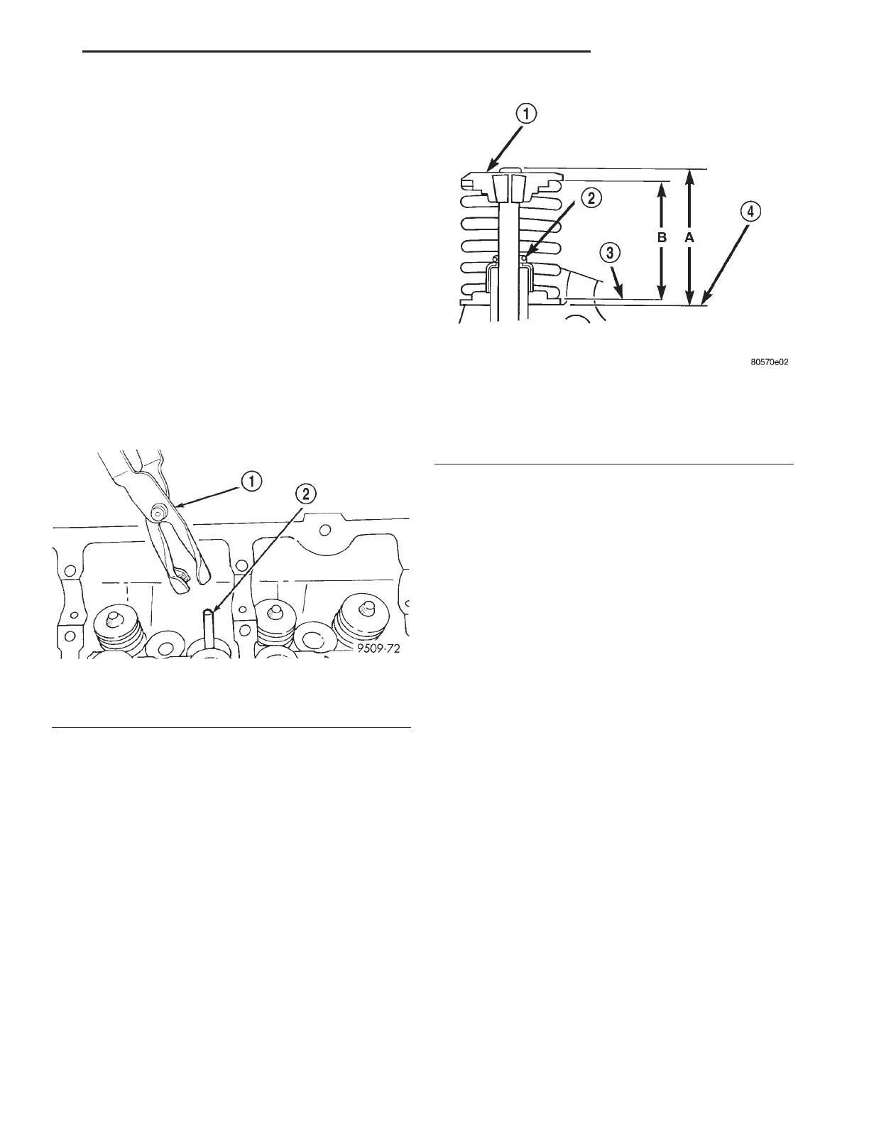
Fig. 86 Valve Seal Garter Spring
1 – SPRING RETAINER
2 – GARTER SPRING
3 – VALVE SPRING SEAT TOP
4 – CYLINDER HEAD SURFACE
LH 3.2/3.5L ENGINE 9 - 121
REMOVAL AND INSTALLATION (Continued)