ber seal. Place valve springs (color-coded end facing
up) and valve retainers into position.
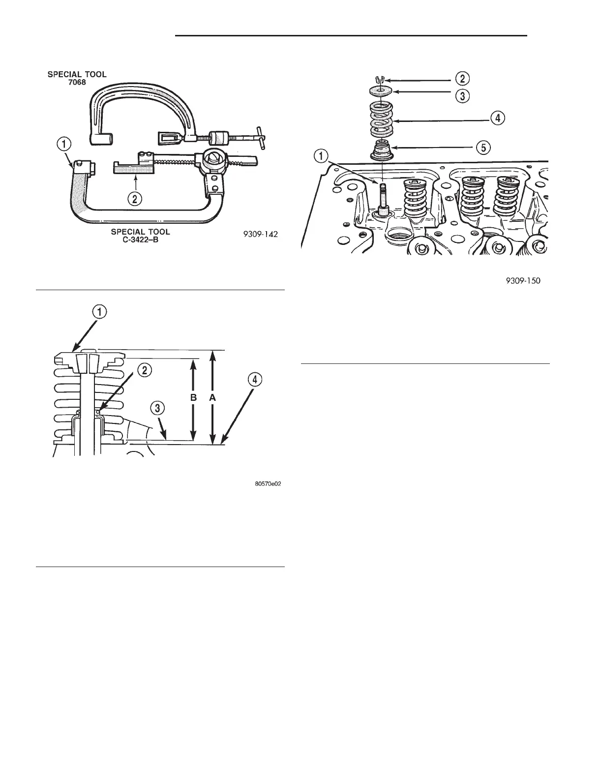
(4) Compress valve springs with a valve spring
compressor install locks and release tool. If valves
and/or seats are reground, measure the
installed height of springs (B) (Fig. 88), make
sure measurements are taken from top of
spring seat to the bottom surface of spring
retainer. If height is greater than 38.75 mm (1.5256
inches), install a.762 mm (0.030 inch.) spacer in head
counterbore under the valve spring seat to bring
spring height back within specification.
TIMING BELT COVERS
REMOVAL
(1) Disconnect negative cable from remote jumper
terminal.
(2) Remove upper radiator crossmember. Refer to
BODY for procedure.
(3) Remove the cooling fan module and accessory
drive belts. Refer to COOLING SYSTEM for proce-
dures.
(4) Use Special Tool 8191 to hold crankshaft
damper while removing center bolt.
(5) Remove crankshaft damper using Special Tools
1023 and C-4685-C2 (Fig. 90).
(6) Remove the lower belt cover located behind the
crankshaft damper (Fig. 92).
(7) Remove the A/C belt guide/lift bracket (Fig. 91).
(8) Remove the stamped steel cover (Fig. 92). Do
not remove the sealer on the cover, it is reus-
able (Fig. 93). If some sealer is missing use Mopart
Engine RTV GEN II to replace the missing sealer.
(9) Remove the left cast cover (Fig. 92).
INSTALLATION
(1) Install the left cast cover (Fig. 92) and genera-
tor/power steering belt tensioner pulley and bracket.
(2) Install the right stamped steel cover (Fig. 92).
(3) Install A/C belt guide/lift bracket (Fig. 91).
(4) Install the lower cover (Fig. 92).
Fig. 87 Valve Spring Compressors
1 – ADAPTER 6537
2 – ADAPTER 6526
Fig. 88 Checking Valve Tip Height and Valve Spring
Installed Height
1 – SPRING RETAINER
2 – GARTER SPRING
3 – VALVE SPRING SEAT TOP
4 – CYLINDER HEAD SURFACE
Fig. 89 Valve, Spring, and Valve Seal—Installation
1 – VALVE
2 – VALVE RETAINING LOCKS
3 – VALVE SPRING RETAINER
4 – VALVE SPRING
5 – VALVE SEAL AND VALVE SPRING SEAT ASSEMBLY
9 - 122 3.2/3.5L ENGINE LH
REMOVAL AND INSTALLATION (Continued)