(7) Slide steering gear and intermediate shaft back
into dash panel sealing boot. Align the steering gear
mounting holes with its mounting holes in crossmem-
ber.
(8) Loosely install the bolts mounting the left side
of the steering gear to the crossmember (Fig. 21).
CAUTION: Tightening the steering gear to cross-
member mounting bolts to the proper torque is very
important.
(9) Install the bolts mounting the right side
mounting bracket for the steering gear to the cross-
member (Fig. 22). Tighten the mounting bolts to a
torque of 58 N·m (43 ft. lbs.).
(10) Tighten the bolts mounting the left side of the
steering gear to the crossmember (Fig. 21) to a
torque of 58 N·m (43 ft. lbs.).
(11) Attach power steering fluid, pressure and
return lines into proper ports of the steering gear
(Fig. 20). Tighten both power steering hose tube nuts
to a torque of 47 N·m (35 ft. lbs.).
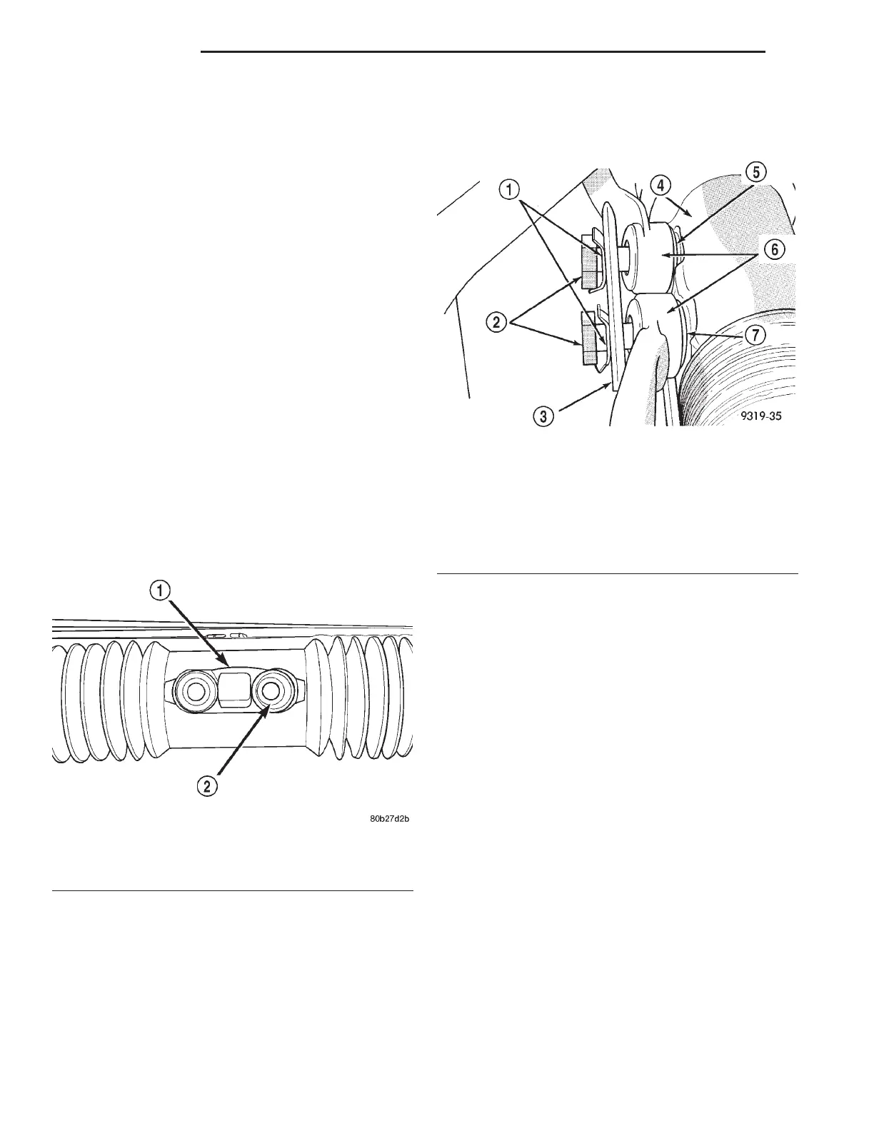
CAUTION: Before installing tie rods on steering
gear be sure the tie rod spacer block inside the
steering gear bellows (Fig. 26) is correctly aligned
with the bolt holes in the rack of the steering gear
and the steering gear bellows.
(12) Align center take off on steering gear with the
tie rod assemblies. Install tie rod attaching bolts and
washers into steering gear. Be sure washers are
installed between tie rods and steering gear
(Fig. 27). Tighten the tie rod to steering gear bolts to
a torque of 82 N·m (60 ft. lbs.).
CAUTION: After tie rod attaching bolts are torqued,
bend attaching bolt retaining tabs against heads of
attaching bolts (Fig. 17).
(13) Install the vacuum hose for the vacuum
booster on intake manifold vacuum port. Install hose
clamp on vacuum hose.
(14) Install the master cylinder on the vacuum
booster. Install the 2 nuts attaching the master cyl-
inder to the vacuum booster. Tighten the master cyl-
inder mounting nuts to a torque of 28 N·m (250 in.
lbs.).
(15) Remove the clamp from the steering wheel
(Fig. 15).
(16) Install the intermediate shaft onto the steer-
ing column shaft. Install steering column coupler
pinch bolt (Fig. 16) and tighten to a torque of 28 N·m
(21 ft. lbs.). Install the pinch bolt nut retaining pin in
pinch bolt.
(17) Install the reinforcement (Fig. 13) on the vehi-
cle. Install the 8 bolts, attaching the reinforcement
(Fig. 13) to the strut towers. Install the bolt (Fig. 13)
attaching the wiper module to the reinforcement..
(18) Install the in-line resonator and inlet hose
(Fig. 14) on the throttle body and air let hose coming
from the lid of the air cleaner housing.
(19) Install the covers (Fig. 12) over the wiper
module and the cowl. Install and securely tighten the
attaching screws.
(20) Install the wiper arms (Fig. 11) on the pivots.
Install and securely tighten the wiper arm to pivot
Fig. 26 Tie Rod Spacer Block
1 – STEERING GEAR BOOT
2 – SPACER BLOCK
Fig. 27 Tie Rod Attachment To Steering Gear
1 – RETAINING TABS
2 – BOLTS
3 – PLATE
4 – STEERING GEAR
5 – WASHER
6 – TIE RODS
7 – WASHER
19 - 16 STEERING LH
REMOVAL AND INSTALLATION (Continued)

 Loading...


