The horizontal aim should be set so that the notch
between the horizontal component of the cut-off and
the 15° portion is approximately at the headlamp
centerline as shown in the illustration. This is not
normally required, but the horizontal adjusters can
be accessed in the outboard area between the lamp
and the crossmember.
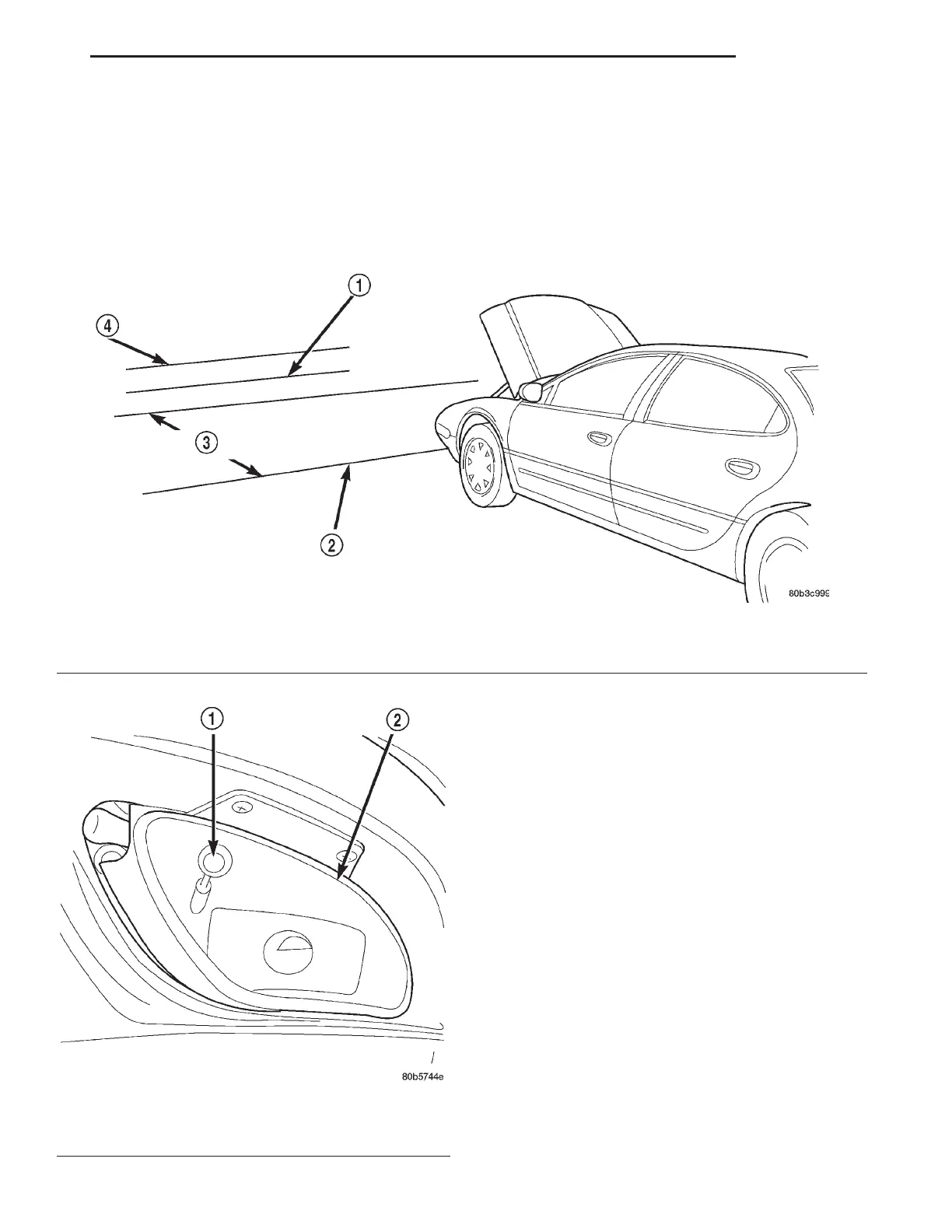
FOG LAMP ALIGNMENT
Prepare an alignment screen. Refer to Alignment
Screen Preparation paragraph in this section. A prop-
erly aligned fog lamp will project a pattern on the
alignment screen 100 mm (4 in.) below the fog lamp
center line and straight ahead. To adjust fog lamp
alignment, rotate the vertical alignment screw (Fig.
3).
Fig. 3 Fog lamp Adjuster Screw
1 – FOG LAMP ADJUSTER SCREW
2 – FRONT FOG LAMP
Fig. 2 Fog Lamp Alignment Screen
1 – TOP OF FOG LAMP HIGH INTENSITY ZONE 64 INS. FROM
HORIZONTAL CENTER LINE
2 – FRONT OF FOG LAMP
3 – 7.62 METERS (25 FT.)
4 – HORIZONTAL CENTER LINE OF FOG LAMPS
LH LAMPS 8L - 7
ADJUSTMENTS (Continued)
2000 LHS, 300M, CONCORDE AND INTREPID