REMOVAL
(1) Raise vehicle on jackstands or centered on a
frame contact type hoist. See Hoisting in the Lubri-
cation and Maintenance section of this manual, for
the required lifting procedure to be used for this
vehicle.
(2) Remove the wheel and tire assembly from the
vehicle.
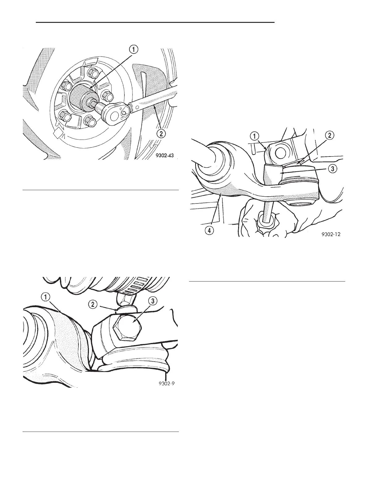
(3) Remove the ball joint stud to steering knuckle
attaching nut and bolt (Fig. 37).
CAUTION: Pulling steering knuckle out from vehi-
cle after releasing from ball joint can separate inner
C/V joint. See Driveshafts.
CAUTION: When lower control arm is separated
from steering knuckle, do not let ball joint seal hit
up against steering knuckle. If ball joint seal hits
steering knuckle, seal damage may occur. If ball
joint seal becomes torn, replace seal before assem-
bling lower control arm to knuckle.
(4) Carefully insert a pry bar between lower con-
trol arm and steering knuckle (Fig. 38). Push down
on pry bar to separate ball joint stud from steering
knuckle (Fig. 38).
(5) Remove tension strut to cradle attaching nut
and washer from end of tension strut (Fig. 39). When
removing tension strut nut, keep strut from turning
by holding tension strut at flat using open end
wrench (Fig. 39). Discard tension strut to cradle
retaining nut. A NEW tension strut to cradle
nut must be used when installing tension strut.
(6) Loosen and remove lower control arm pivot
bushing to cradle assembly pivot bolt (Fig. 40).
(7) Separate lower control arm and tension strut
from the cradle as an assembly. Lower control arm is
removed from cradle, by first removing pivot bushing
from cradle and then sliding tension strut out of iso-
lator bushing (Fig. 41). Refer to TENSION STRUT in
the DISASSEMBLY AND ASSEMBLY section in this
group for the required procedure.
(8) Inspect lower control arm and tension strut
(Fig. 42) for distortion. Check all bushings for signs
of sever deterioration. Replace any bushings that
show signs of sever deterioration.
Fig. 36 Torquing Hub And Bearing Retaining Nut
1 – HUB/BEARING
2 – TORQUE WRENCH
Fig. 37 Control Arm To Steering Knuckle
Attachment
1 – LOWER CONTROL ARM
2 – BALL JOINT STUD
3 – CLAMP NUT AND BOLT
Fig. 38 Separating Ball Joint From Steering Knuckle
1 – STEERING KNUCKLE
2 – BALL JOINT STUD
3–PRYBAR
4 – LOWER CONTROL ARM
LH SUSPENSION 2 - 25
REMOVAL AND INSTALLATION (Continued)