(7) Rotate crankshaft so that the connecting rod
journal is on the center of the cylinder bore. Insert
rod and piston into cylinder bore and guide rod over
the crankshaft journal (Fig. 101).
CAUTION: Do Not interchange piston assemblies
bank to bank, as engine damage may occur.
(8) Tap the piston down in cylinder bore, using a
hammer handle. At the same time, guide connecting
rod into position on connecting rod journal.
(9) Lubricate rod bolts and bearing surface with
engine oil. Install connecting rod cap and bearing.
Tighten bolts to 27 N·m (20 ft. lbs.) Plus 1/4 turn.
ENGINE CORE AND OIL PLUGS
REMOVAL
Using a blunt tool such as a drift and a hammer,
strike the bottom edge of the cup plug. With the cup
plug rotated, grasp firmly with pliers or other suit-
able tool and remove plug (Fig. 103).
CAUTION: Do not drive cup plug into the casting
as restricted cooling can result and cause serious
engine problems.
INSTALLATION
Thoroughly clean inside of cup plug hole in cylin-
der block or head. Be sure to remove old sealer.
Lightly coat inside of cup plug hole with Mopart
Stud and Bearing Mount. Make certain the new plug
is cleaned of all oil or grease. Using proper drive
plug, drive plug into hole so that the sharp edge of
the plug is at least 0.5 mm (0.020 in.) inside the
lead-in chamfer.
It is not necessary to wait for curing of the sealant.
The cooling system can be refilled and the vehicle
placed in service immediately.
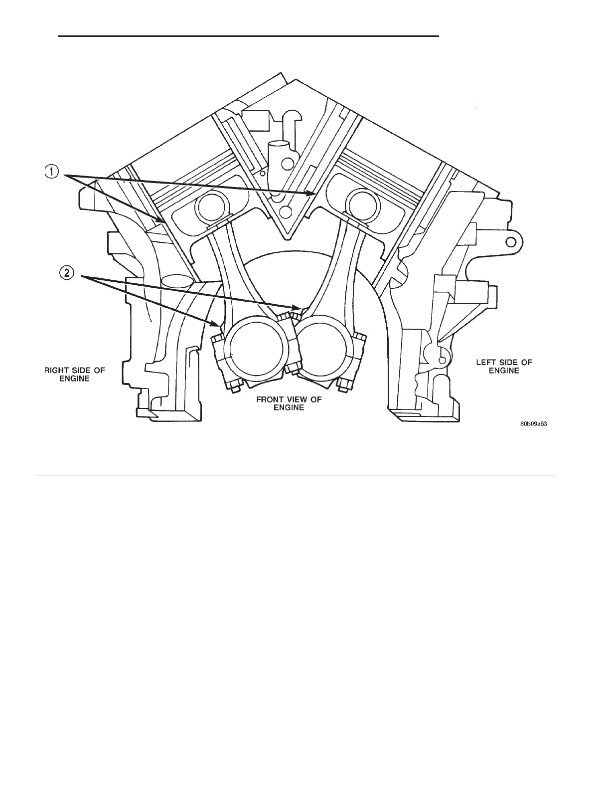
Fig. 102 Piston and Connecting Rod Positioning
1 – MAJOR THRUST SIDE OF PISTON
2 – OIL SQUIRT HOLE
LH 2.7L ENGINE 9 - 61
REMOVAL AND INSTALLATION (Continued)