DISASSEMBLY AND ASSEMBLY
OIL PUMP
(1) Remove the pressure relief valve by remove the
threaded retaining cap from the oil pump housing.
CAUTION: Oil pump pressure relief valve must be
installed as shown in (Fig. 104) or engine damage
may occur.
(2) Remove spring and relief valve.
(3) Remove oil pump cover screws and lift off cover
plate (Fig. 105).
(4) Remove pump rotors.
(5) Wash all parts in a suitable solvent. Inspect
components carefully for damage or wear. Refer to
Cleaning and Inspection, Oil Pump in this section for
procedures.
(6) Tighten cover screws to 12 N·m (105 in. lbs.)
(Fig. 105). Tighten oil pressure relief valve retaining
cap to 12 N·m (105 in. lbs.) (Fig. 104).
Fig. 103 Core Hole Plug Removal
1 – CYLINDER BLOCK
2 – REMOVE PLUG WITH PLIERS
3 – STRIKE HERE WITH HAMMER
4 – DRIFT PUNCH
5 – CUP PLUG
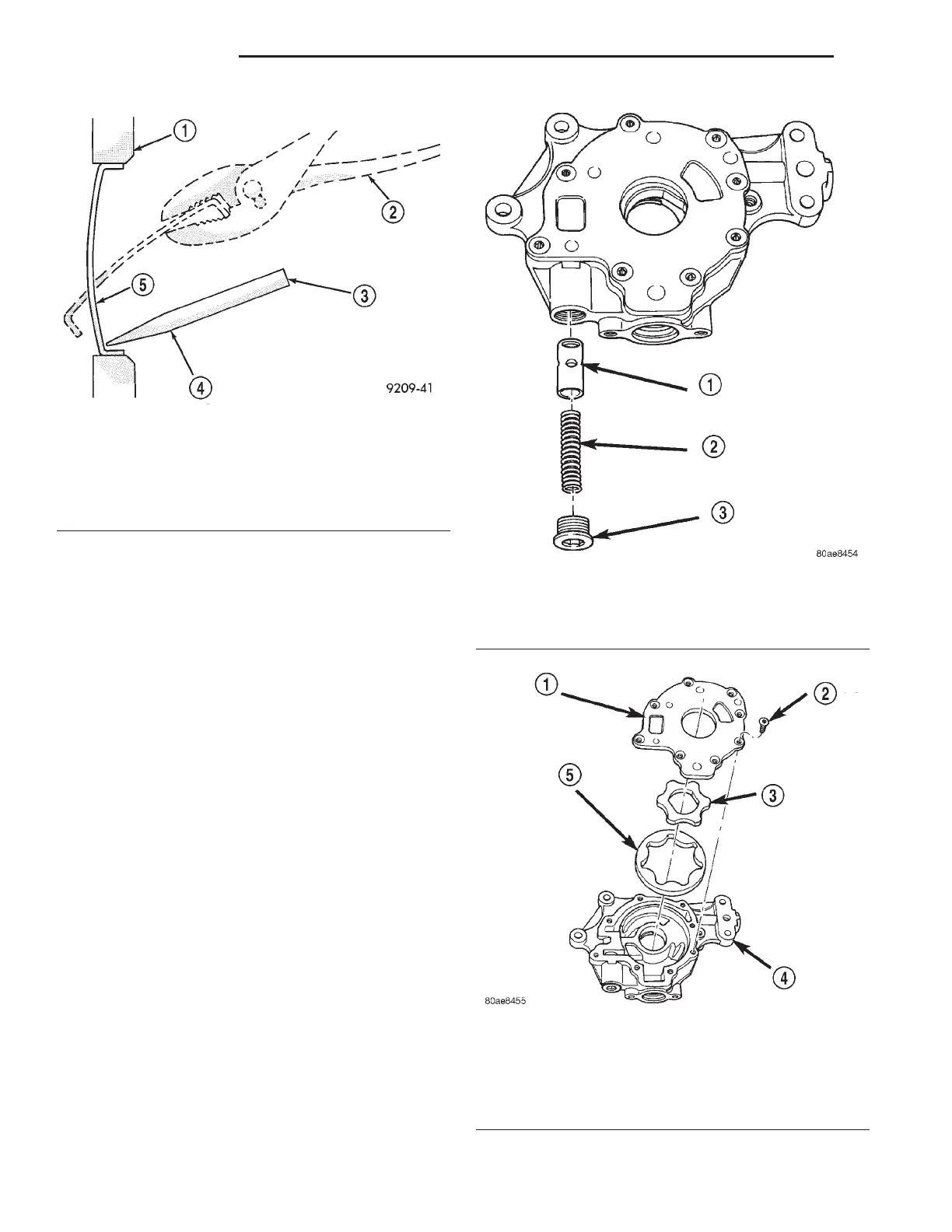
Fig. 104 Oil Pressure Relief Valve
1 – RELIEF VALVE
2 – SPRING
3 – RETAINER CAP
Fig. 105 Oil Pump
1 – OIL PUMP COVER
2 – SCREWS (8)
3 – OIL PUMP INNER ROTOR
4 – OIL PUMP HOUSING
5 – OIL PUMP OUTER ROTOR
9 - 62 2.7L ENGINE LH
REMOVAL AND INSTALLATION (Continued)