CLEANING AND INSPECTION
INTAKE MANIFOLD
Check for:
• Damage and cracks of each section.
• Clogged water passages in end cross over and
clogged gas passages.
EXHAUST MANIFOLD
Inspect exhaust manifolds for damage or cracks
and check distortion of the cylinder head mounting
surface with a straightedge and thickness gauge.
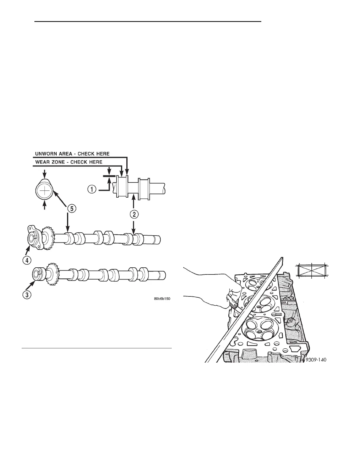
CAMSHAFT
(1) Inspect camshaft bearing journals for damage
and binding (Fig. 106). If journals are binding, check
the cylinder head for damage. Also check cylinder
head oil holes for clogging.
(2) Inspect camshaft sprockets for excessive wear.
Replace camshafts if necessary.
(3) Check the cam lobe surfaces for abnormal wear
and damage. Replace camshaft if defective. Measure
the actual wear (Fig. 106) and replace, if out of lim-
its—standard value is 0.0254 mm (0.001 in.); wear
limit is 0.254 mm (0.010 in.).
CYLINDER HEAD
CLEANING
(1) Use a gasket removal compound to soften the
old gasket material.
CAUTION: When cleaning the cylinder head and
block mating surfaces, do not use a metal scraper
because the sealing surfaces could be cut or
ground. Instead, use a wooden or plastic scraper.
(2) Make sure the gasket and/or foreign material
does not enter the oil feed hole or the oil return
holes.
INSPECTION
(1) Before cleaning, check for leaks, damage and
cracks.
(2) Clean cylinder head and oil passages.
(3) Check cylinder head for flatness (Fig. 107).
(4) Cylinder head must be flat within:
• Standard dimension = less than 0.05 mm (0.002
inch.)
• Service Limit = 0.2 mm (0.008 inch.)
• Grinding Limit = Maximum of 0.2 mm (0.008
inch.) is permitted.
CAUTION: 0.20 mm (0.008 in.) MAX is a combined
total dimension of the stock removal limit from cyl-
inder head and block top surface (Deck) together.
CAMSHAFT FOLLOWER
Inspect the cam follower assembly for wear or
damage (Fig. 108). Replace as necessary.
VALVE INSPECTION
(1) Clean valves thoroughly and replace burned,
warped and cracked valves.
(2) Measure valve stems for wear (Fig. 109). Refer
to Engine Specifications.
Fig. 106 Camshaft Inspection
1 – ACTUAL WEAR
2 – BEARING JOURNAL
3 – EXHAUST CAMSHAFT
4 – INTAKE CAMSHAFT
5 – LOBE
Fig. 107 Checking Cylinder Head Flatness—Typical
LH 2.7L ENGINE 9 - 63