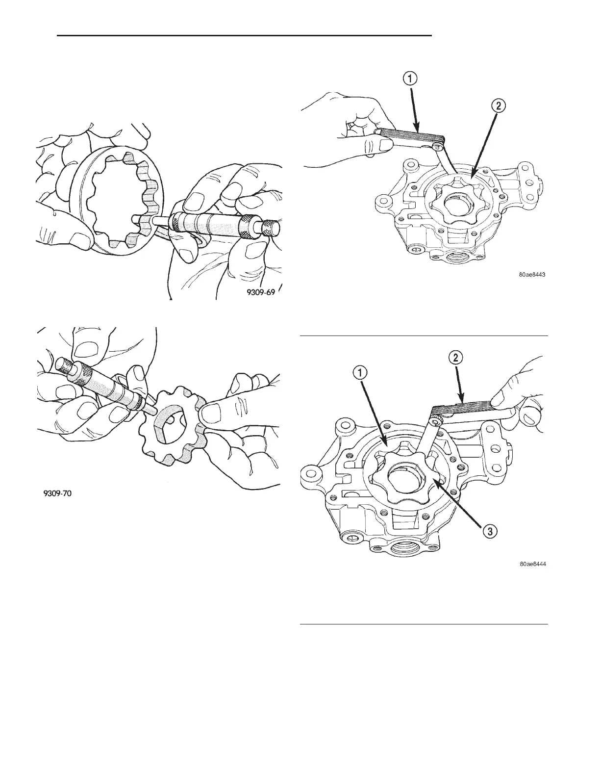
(3) Measure thickness and diameter of outer rotor.
If outer rotor thickness measures 9.474 mm (0.373
in.) or less (Fig. 112), or if the diameter is 89.174 mm
(3.5108 inches.) or less, replace outer rotor.
(4) If inner rotor measures 9.474 mm (0.373 inch.)
or less replace inner rotor (Fig. 113).
(5) Slide outer rotor into body, press to one side
with fingers and measure clearance between rotor
and body (Fig. 114). If measurement is 0.39 mm
(0.015 inch.) or more, replace body only if outer rotor
is in specifications.
(6) Install inner rotor into body. If clearance
between inner and outer rotors (Fig. 115) is 0.20 mm
(0.008 inch.) or more, replace both rotors.
(7) Place a straightedge across the face of the body,
between bolt holes. If a feeler gauge of 0.077 mm
(0.003 inch.) or more can be inserted between rotors
and the straightedge, replace pump assembly (Fig.
116) ONLY if rotors are in specs.
(8) Inspect oil pressure relief valve plunger for
scoring and free operation in its bore. Small marks
may be removed with 400-grit wet or dry sandpaper.
(9) The relief valve spring has a free length of
approximately 49.5 mm (1.95 inches) it should test
between 23 – 25 pounds when compressed to 34 mm
(1.34 in.). Replace spring that fails to meet specifica-
tions.
Fig. 112 Measuring Outer Rotor Thickness
Fig. 113 Measuring Inner Rotor Thickness
Fig. 114 Measuring Outer Rotor Clearance in
Housing
1 – FEELER GAUGE
2 – OUTER ROTOR
Fig. 115 Measuring Clearance Between Rotors
1 – OUTER ROTOR
2 – FEELER GAUGE
3 – INNER ROTOR
LH 2.7L ENGINE 9 - 65
CLEANING AND INSPECTION (Continued)