PISTON RING—FITTING
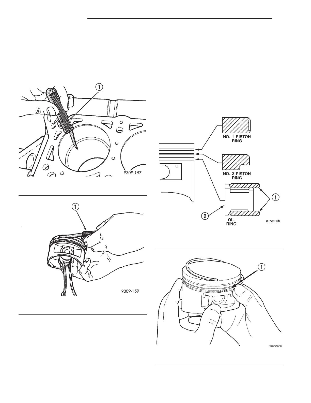
(1) Wipe cylinder bore clean. Insert ring and push
down with piston to ensure it is square in bore. The
ring gap measurement must be made with the ring
positioning at least 12 mm (0.50 inch.) from bottom
of cylinder bore. Check gap with feeler gauge (Fig.
22). Refer to Engine Specifications.
(2) Check piston ring to groove clearance: (Fig. 23).
Refer to Engine Specifications.
PISTON RINGS—INSTALLATION
(1) The No. 1 and No. 2 piston rings have a differ-
ent cross section. Insure that the No. 2 ring is
installed with manufacturers I.D. mark (dot) facing
up, towards top of the piston (Fig. 24).
CAUTION: Install piston rings in the following
order:
(2) Oil ring expander.
(3) Upper oil ring side rail.
(4) Lower oil ring side rail.
(5) No. 2 Intermediate piston ring.
(6) No. 1 Upper piston ring.
(7) Install the side rail by placing one end between
the piston ring groove and the expander. Hold end
firmly and press down the portion to be installed
until side rail is in position. Do not use a piston
ring expander during this step (Fig. 25).
Fig. 22 Check Gap on Piston Rings
1 – FEELER GAUGE
Fig. 23 Measuring Piston Ring Side Clearance
1 – FEELER GAUGE
Fig. 24 Piston Ring—Installation
1 – SIDE RAIL
2 – SPACER EXPANDER
Fig. 25 Side Rail—Installation
1 – SIDE RAIL END
9 - 96 3.2/3.5L ENGINE LH
SERVICE PROCEDURES (Continued)