(8) Install upper side rail first and then the lower
side rail.
(9) Install No. 2 piston ring and then No. 1 piston
ring (Fig. 26).
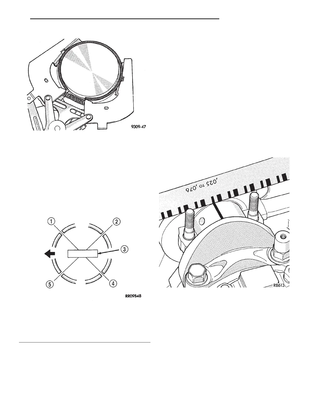
(10) Position piston ring end gaps as shown in
(Fig. 27).
(11) Position oil ring expander gap at least 45°
from the side rail gaps but not on the piston pin cen-
ter or on the thrust direction. Staggering ring gap is
important for oil control.
CONNECTING ROD BEARING—INSTALLATION
Fit all rods on one bank until complete.
The bearing caps are not interchangeable and
should be marked at removal to insure correct
assembly.
The bearing shells must be installed with the
tangs inserted into the machined grooves in the rods
and caps. Install cap with the tangs on the same side
as the rod.
Limits of taper or out-of-round on any crankshaft
journals should be held to 0.015 mm (0.0006 in.).
Bearings are available in 0.025 mm (0.001 in.) and
0.254 mm (0.010 in.) undersize. Install the bear-
ings in pairs. Do not use a new bearing half
with an old bearing half. Do not file the rods or
bearing caps.
(1) Follow procedure specified in the Standard Ser-
vice Procedure Section for Measuring Main Bearing
Clearance and Connecting Rod Bearing Clearance
(Fig. 28). Refer to Engine Specifications.
NOTE: The rod bearing bolts should be examined
before reuse. If the threads are necked down the
bolts should be replaced (Fig. 29).
(2) Necking can be checked by holding a scale or
straight edge against the threads. If all the threads
do not contact the scale the bolt should be replaced.
(3) Before installing the nuts the threads should
be oiled with engine oil.
(4) Install nuts on each bolt finger tight then alter-
nately torque each nut to assemble the cap properly.
(5) Tighten the nuts to 54 N·m PLUS 1/4 turn (40
ft. lbs. PLUS 1/4 turn).
(6) Using a feeler gauge, check connecting rod side
clearance (Fig. 30). Refer to Engine Specifications.
Fig. 26 Upper and Intermediate Rings—Installation
Fig. 27 Piston Ring End Gap Position
1 – SIDE RAIL UPPER
2 – NO. 1 RING GAP
3 – PISTON PIN
4 – SIDE RAIL LOWER
5 – NO. 2 RING GAP AND SPACER EXPANDER GAP
Fig. 28 Checking Connecting Rod Bearing
Clearance—Typical
LH 3.2/3.5L ENGINE 9 - 97
SERVICE PROCEDURES (Continued)