CRANKSHAFT END PLAY—CHECKING
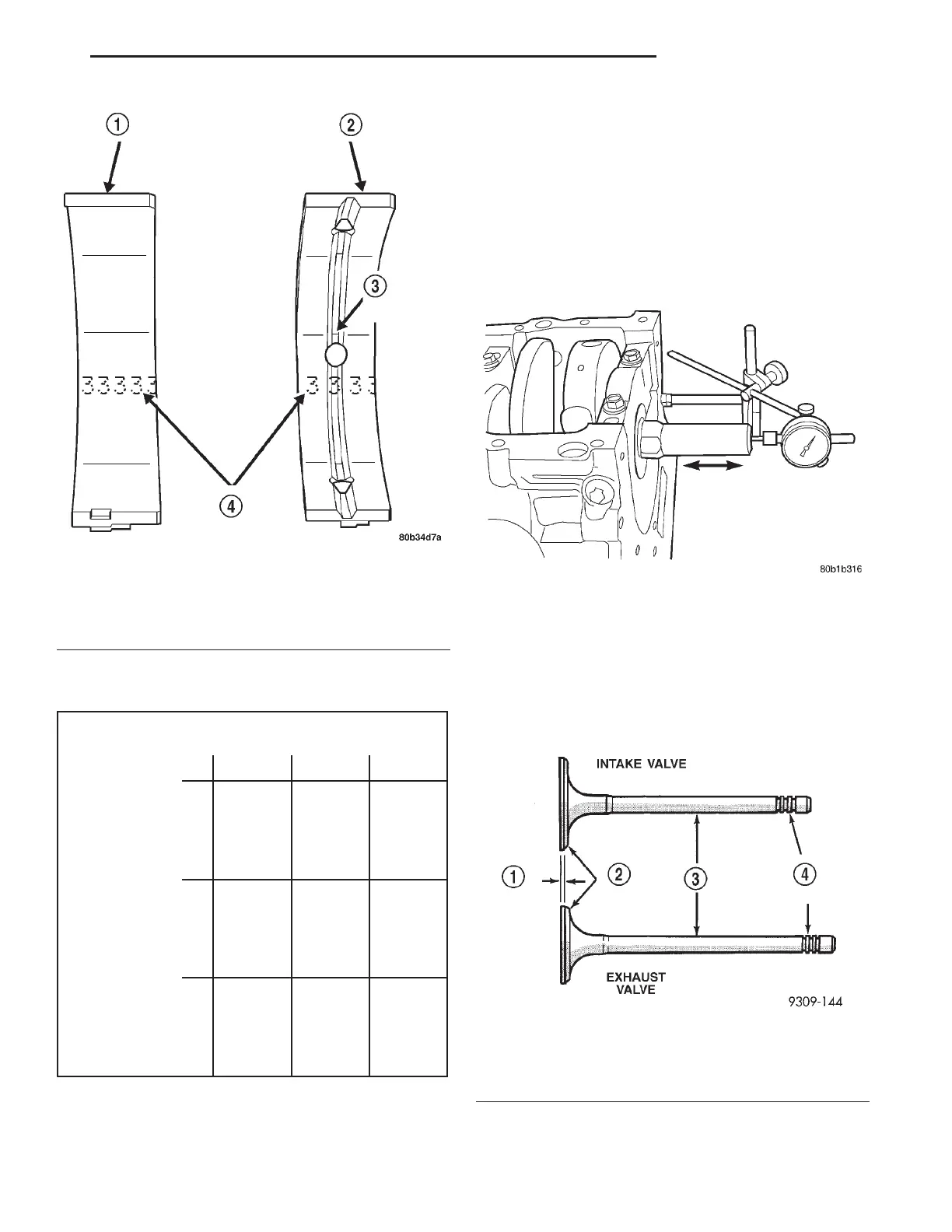
(1) Using Dial Indicator C-3339 and Mounting
Post L-4438, attach to front of engine, locating probe
perpendicular on nose of crankshaft (Fig. 34).
(2) Move crankshaft all the way to the rear of its
travel.
(3) Zero the dial indicator.
(4) Move crankshaft all the way to the front and
read the dial indicator. Refer to Engine Specifica-
tions.
VALVE AND VALVE SEAT—REFACING
The intake and exhaust valves have a 44.5 to 45
degree face angle. The valve seats have a 45 to 45.5
degree face angle. The valve face and valve seat
angles are shown in (Fig. 36).
VALVES
(1) Inspect the remaining margin after the valves
are refaced (Fig. 35). Refer to Engine Specifications.
Fig. 33 Main Bearing Grade Marks
1 – LOWER MAIN BEARING
2 – UPPER MAIN BEARING
3 – OIL FEED HOLE AND GROOVE
4 – GRADE SELECTION INK MARKS
MAIN BEARING SELECTION CHART—3.2/3.5L
Main Bearing Bore Grade
Marks
123
A
(3)
standard
(2) +003
mm
(+0.0002
in.)
(1)
+0.006
mm
(+0.0003
in.)
Crankshaft
Main Journal
Grade Marks
B
(4)
-0.003
mm
(-0.0002
in.)
(3)
standard
(2) +003
mm
(+0.0002
in.)
C
(5)
-0.006
mm
(-0.0003
in.)
(4)
-0.003
mm
(-0.0002
in.)
(3)
standard
Fig. 34 Checking Crankshaft End Play
Fig. 35 Intake and Exhaust Valves
1 – MARGIN
2–FACE
3 – STEM
4 – VALVE SPRING RETAINER LOCK GROOVES
LH 3.2/3.5L ENGINE 9 - 99
SERVICE PROCEDURES (Continued)