VALVE SEATS
(1) When refacing valve seats, it is important that
the correct size valve guide pilot be used for reseat-
ing stones. A true and complete surface must be
obtained.
(2) Measure the concentricity of valve seat using
dial indicator. Total runout should not exceed 0.051
mm (0.002 inch.) total indicator reading.
(3) Inspect the valve seat with Prussian blue to
determine where the valve contacts the seat. To do
this, coat valve seat LIGHTLY with Prussian blue
then set valve in place. Rotate the valve with light
pressure. If the blue is transferred to the center of
valve face, contact is satisfactory. If the blue is trans-
ferred to top edge of valve face, then lower valve seat
with a 15 degree stone. If the blue is transferred to
the bottom edge of valve face, then raise valve seat
with a 65 degree stone.
NOTE: Valve seats which are worn or burned can
be reworked, provided that correct angle and seat
width are maintained. Otherwise cylinder head must
be replaced.
(4) When seat is properly positioned the width of
the intake seats should be 0.75 to 1.25 mm (0.0296 to
0.0493 in.) and exhaust seats should be 1.25 to 1.75
mm (0.049 to 0.069 in.) (Fig. 36).
(5) Check the valve spring installed height after
refacing the valve and seat (Fig. 38).
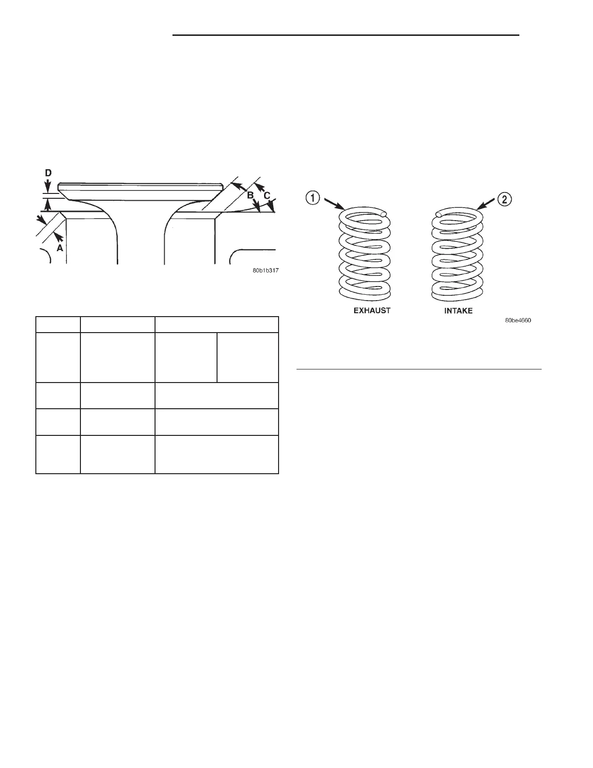
VALVE SPRING IDENTIFICATION
The valve springs are of two different lengths and
are wound in different directions. The valve springs
are color coded, intake spring is right hand coil direc-
tion with orange dye on the top coils and the exhaust
spring is left hand coil direction with a yellow dye on
the top coils (Fig. 37).
VALVE INSTALLATION
(1) Coat valve stems with clean engine oil and
insert them in cylinder head.
(2) If valves or seats have been reground, check
valve tip height (A) (Fig. 38). If valve tip height is
greater than 43.65 mm (1.7185 in.) intake or 45.98
mm (1.8102 in.) exhaust, grind valve tip until within
specifications. Make sure measurement is taken from
cylinder head surface to the top of valve stem.
(3) Install valve seal/spring seat assembly over
valve guides on all valve stems (Fig. 39). Ensure that
the garter spring is intact around the top of the rub-
ber seal. Place valve springs (color-coded end facing
up) and valve retainers into position.
(4) Compress valve springs with a valve spring
compressor, install locks and release tool. If valves
and/or seats are reground, measure the
installed height of springs (B) (Fig. 38), make
sure measurements are taken from top of
spring seat to the bottom surface of spring
retainer. If height is greater than 38.75 mm (1.5256
in.), install a 0.762 mm (0.030 in.) spacer in head
counterbore under the valve spring seat to bring
spring height back within specification.
Fig. 36 Valve Seats
ITEM DESCRIPTION SPECIFICATION
A Seat Width Intake:
0.75 – 1.25
mm (0.030
– 0.049 in.)
Exhaust:
1.25 – 1.75
mm (0.049
– 0.069 in.)
B Face Angle Intake & Exhaust: 44.5 –
45°
C Seat Angle Intake & Exhaust: 45 –
45.5°
D Seat Contact
Area
Valve to seat contact
must be at center of valve
face.
Fig. 37 Valve Spring Identification
1 – YELLOW DYE
2 – ORANGE DYE
9 - 100 3.2/3.5L ENGINE LH
SERVICE PROCEDURES (Continued)