REMOVAL AND INSTALLATION
ENGINE MOUNTS—LEFT AND RIGHT
REMOVAL
(1) Raise vehicle on hoist.
(2) Remove the isolator attaching nuts from top of
the mounting bracket (Fig. 40).
(3) Support the engine with a jack and a block of
wood across the full width of the oil pan.
(4) Remove the lower attaching nuts from the bot-
tom of the isolator to the frame (Fig. 40).
(5) Raise engine carefully with jack enough to
remove the isolator with heat shield from its mount.
INSTALLATION
(1) Install isolator mount with heat shield onto the
frame.
(2) Lower the engine onto the isolator mount.
(3) Remove jack from vehicle.
(4) Tighten the isolator to frame nuts to 61 N·m
(45 ft. lbs.) (Fig. 40).
(5) Install the upper attaching nuts to mount and
tighten to 61 N·m (45 ft. lbs.) (Fig. 40).
(6) Lower vehicle.
ENGINE HYDRO-MOUNT ISOLATORS
Engine hydro-mounts may show surface cracks,
this will not effect performance and hydro-mount
should not be replaced. Only replace the engine
hydro-mounts when leaking fluid:
• Driveshaft Diagnosis. Refer to DIFFERENTIAL
AND DRIVELINE.
• Any front end structural damage (after repair).
• Isolator replacement.
ENGINE MOUNT—REAR
REMOVAL
(1) Raise vehicle on hoist.
(2) Support transaxle with a jack.
(3) Remove isolator nuts from the mount to tran-
saxle mount bracket (Fig. 40).
(4) Remove rear mount isolator bolts to crossmem-
ber and remove mount (Fig. 40).
INSTALLATION
(1) Position isolator onto crossmember.
(2) Install bolts attaching isolator to crossmember
and tighten to 33 N·m (250 in. lbs.) (Fig. 40).
(3) Lower transaxle onto isolator.
(4) Install isolator nuts and tighten to 61 N·m (45
ft. lbs.) (Fig. 40).
(5) Lower vehicle.
STRUCTURAL COLLAR
REMOVAL
(1) Raise vehicle on hoist.
(2) Remove bolts attaching structural collar to oil
pan and transmission housing (Fig. 41).
(3) Remove collar (Fig. 41).
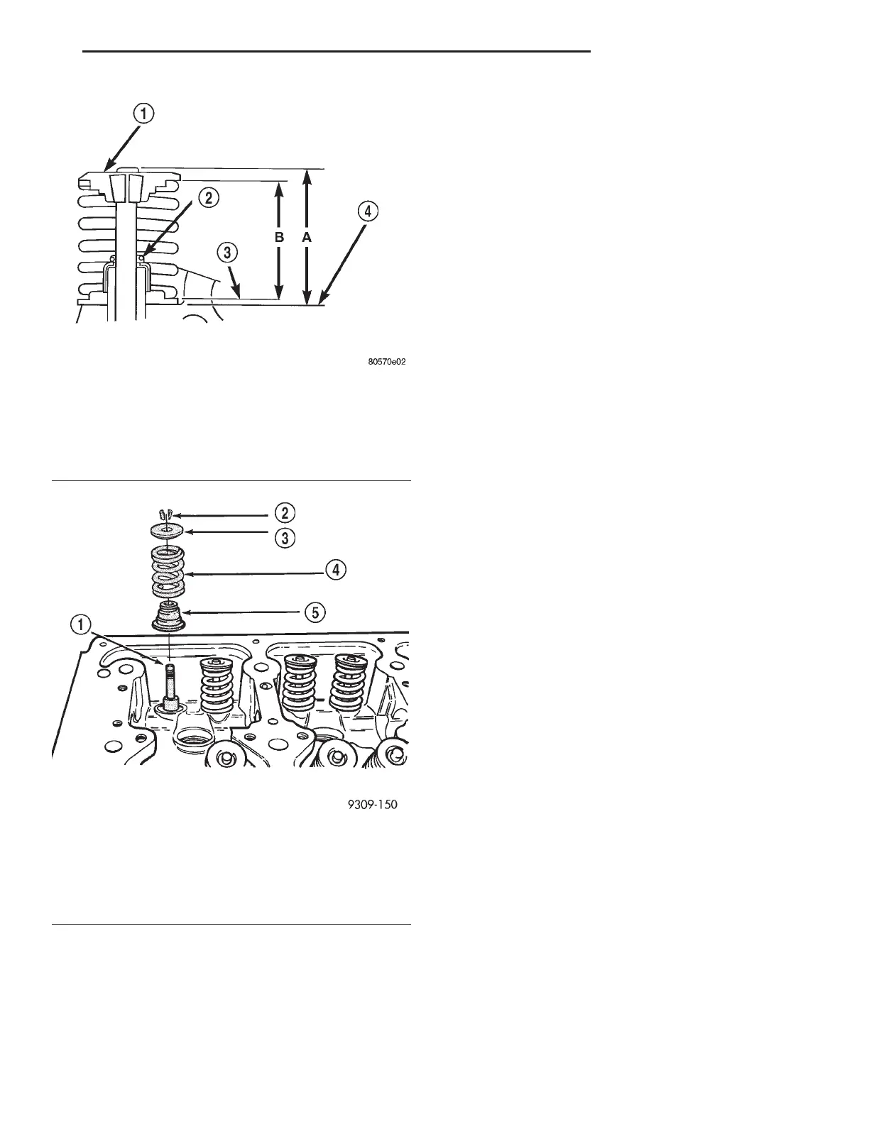
Fig. 38 Checking Valve Tip Height and Valve Spring
Installed Height
1 – SPRING RETAINER
2 – GARTER SPRING
3 – VALVE SPRING SEAT TOP
4 – CYLINDER HEAD SURFACE
Fig. 39 Valve Seal and Spring—Installation
1 – VALVE
2 – VALVE RETAINING LOCKS
3 – VALVE SPRING RETAINER
4 – VALVE SPRING
5 – VALVE SEAL AND VALVE SPRING SEAT ASSEMBLY
LH 3.2/3.5L ENGINE 9 - 101
SERVICE PROCEDURES (Continued)