INSTALLATION
(1) Clean and inspect gasket sealing surfaces.
NOTE: Intake gaskets can be reused, provided they
are free of cuts or tears.
(2) Inspect gasket for cuts or tears. Replace gas-
kets as necessary.
(3) Install intake manifold and hand start all
attaching bolts.
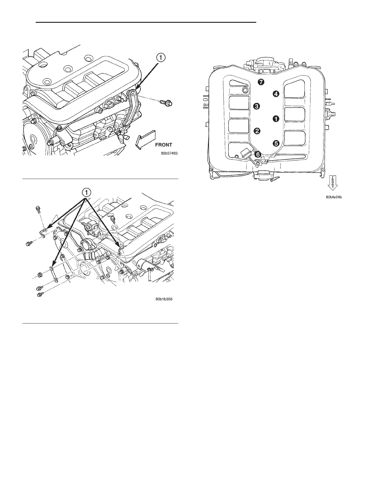
(4) Tighten bolts gradually in sequence shown in
(Fig. 53) until a torque of 12 N·m (105 in. lbs.) is
obtained.
(5) Install right side (Fig. 50) and left side (Fig.
51) intake manifold supports.
(6) Install manifold support brackets at front cor-
ners and at MTV (Fig. 52).
(7) Tighten fastener attaching throttle body to sup-
port bracket.
(8) Connect vacuum lines to the following:
• Secondary Runner Valve (SRV) Reservoir
• Speed Control Reservoir
• Positive Crankcase Ventilation (PCV) Valve
• Proportional Purge Solenoid
• Power Brake Booster
(9) Connect electrical connectors to the following:
• Secondary Runner Valve (SRV)
• Manifold Tuning Valve (MTV)
• Throttle Position Sensor (TPS)
• Idle Air Control (IAC)
• Intake Air Temperature/Manifold Absolute Pres-
sure (TMAP)
• Vacuum Reservoir Solenoid
(10) Install EGR tubes to intake manifold. Refer to
EMISSION CONTROL SYSTEM for procedure.
(11) Install throttle and speed control cables to
bracket and throttle arm.
(12) Install air cleaner housing and inlet tube.
(13) Connect negative cable to remote jumper ter-
minal.
INTAKE MANIFOLD—LOWER
WARNING: RELEASE FUEL SYSTEM PRESSURE
BEFORE SERVICING SYSTEM COMPONENTS. SER-
VICE VEHICLES IN WELL VENTILATED AREAS AND
AVOID IGNITION SOURCES. NEVER SMOKE WHILE
SERVICING THE VEHICLE.
Fig. 51 Intake Manifold Support—Left Side
1 – SUPPORT BRACKET
Fig. 52 Intake Manifold Supports—Front
1 – SUPPORT BRACKETS
Fig. 53 Upper Intake Manifold Tightening Sequence
LH 3.2/3.5L ENGINE 9 - 107
REMOVAL AND INSTALLATION (Continued)
 Loading...


