DocID13284 Rev 2 273/564
UM0404 High-speed synchronous serial interface
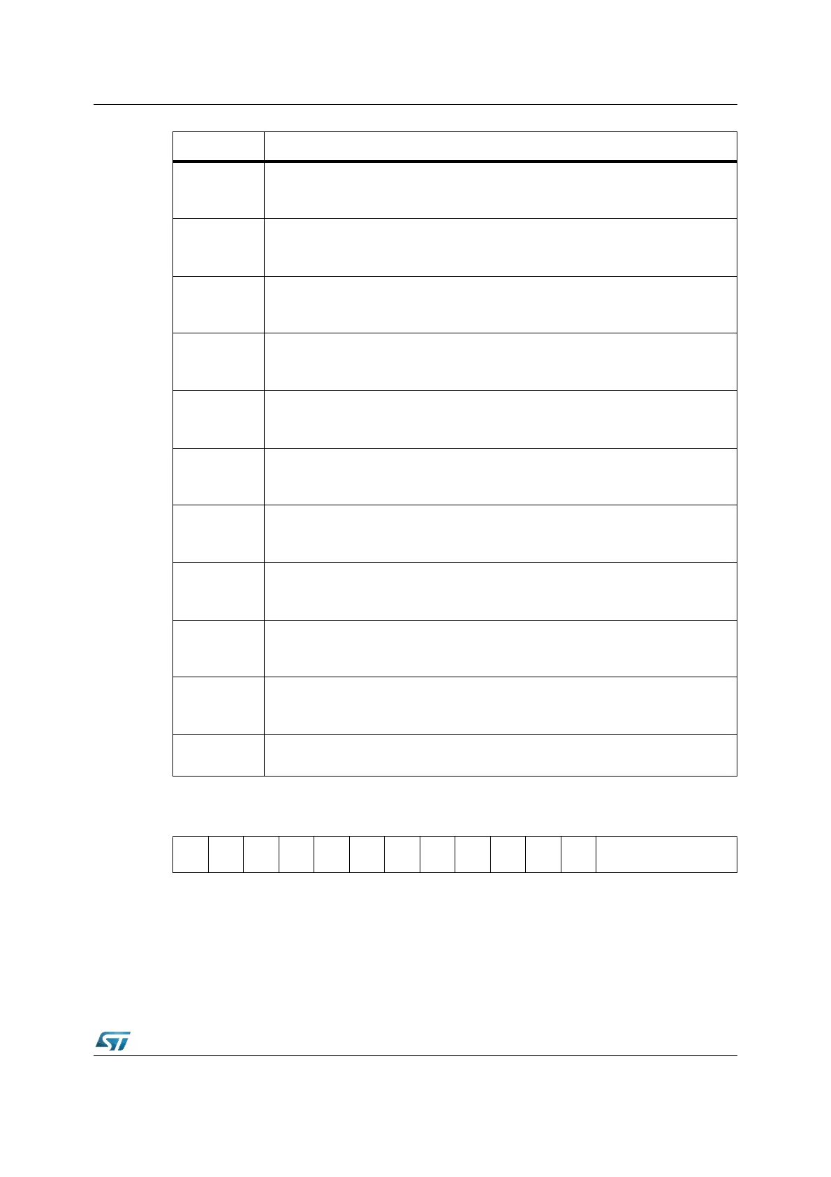
SSCCON (FFB2h / D9h) SFR Reset Value: 0000h
Bit Function (programming mode, SSCEN = ‘0’)
SSCBM
SSC Data Width Selection
0: Reserved. Do not use this combination.
1...15: Transfer Data Width is 2...16-bit [(SSCBM)+1]
SSCHB
SSC Heading Control bit
0: Transmit/Receive LSB First
1: Transmit/Receive MSB First
SSCPH
SSC Clock Phase Control bit
0: Shift transmit data on the leading clock edge, latch on trailing edge
1: Latch receive data on leading clock edge, shift on trailing edge
SSCPO
SSC Clock Polarity Control bit
0: Idle clock line is low, leading clock edge is low-to-high transition
1: Idle clock line is high, leading clock edge is high-to-low transition
SSCTEN
SSC Transmit Error Enable bit
0: Ignore transmit errors
1: Check transmit errors
SSCREN
SSC Receive Error Enable bit
0: Ignore receive errors
1: Check receive errors
SSCPEN
SSC Phase Error Enable bit
0: Ignore phase errors
1: Check phase errors
SSCBEN
SSC Baudrate Error Enable bit
0: Ignore baudrate errors
1: Check baudrate errors
SSCAREN
SSC Automatic Reset Enable bit
0: No additional action upon a baudrate error
1: The SSC is automatically reset upon a baudrate error
SSCMS
SSC Master Select bit
0: Slave Mode. Operate on shift clock received via SCLK.
1: Master Mode. Generate shift clock and output it via SCLK.
SSCEN
SSC Enable bit = ‘0’
Transmission and reception disabled. Access to control bits.
1514131211109876543210
SSC
EN=1
SSC
MS
-
SSC
BSY
SSC
BE
SSC
PE
SSC
RE
SSC
TE
- - - - SSCBC
RW RW RW RW RW RW RW RW