I
2
C interface UM0404
404/564 DocID13284 Rev 2
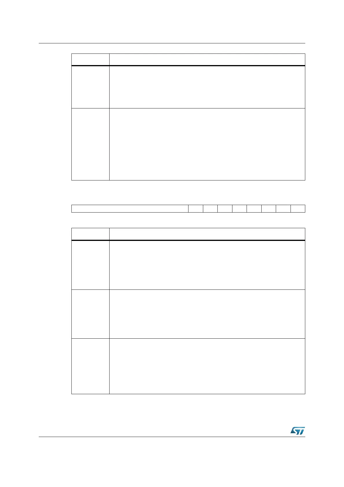
I2CSR1 (EA02h) XBUS Reset Value: 0000h
ENGC
Enable General Call
This bit is set and cleared by software. It is also cleared by hardware when the
interface is disabled (PE
= 0). The 00h General Call address is acknowledged (01h
ignored).
‘0’: General Call disabled.
‘1’: General Call enabled.
PE
Peripheral Enable
This bit is set and cleared by software.
‘0’: Peripheral disabled
‘1’: Master/Slave capability
Notes:
– ‘0’: all the bits of the I2CCR, I2CSR1 and I2CSR2 registers except the STOP bit
are reset.
– ‘1’: the corresponding I/O pins are selected by hardware as alternate functions.
To enable the I
2
C interface, write the I2CCR register TWICE with PE = 1 as the first
write only activates the interface (only PE is set).
15 14 13 12 11 10 9 8 7 6 5 4 3 2 1 0
– EVF ADD10 TRA BUSY BTF ADSL M/SL SB
RRRRRRRR
Bit Function
SB
Start bit (Master mode)
This bit is set by hardware as soon as the Start condition is generated (following a
write START
= 1). An interrupt is generated if ITE = 1. It is cleared by software
reading I2CSR1 register followed by writing the address byte in I2CDR register. It is
also cleared by hardware when the interface is disabled (PE = 0).
‘0’: No Start condition.
‘1’: Start condition generated.
M/SL
Master/Slave
This bit is set by hardware as soon as the interface is in Master mode (writing
START = 1). It is cleared by hardware after detecting a Stop condition on the bus or
a loss of arbitration (ARLO
= 1). It is also cleared when the interface is disabled
(PE
= 0).
‘0’: Slave mode
‘1’: Master mode
ADSL
Address matched (Slave mode)
This bit is set by hardware as soon as the received slave address matched with the
OAR register content or a general call is recognized. An interrupt is generated if
ITE
= 1. It is cleared by software reading I2CSR1 register or by hardware when the
interface is disabled (PE
= 0).
The SCL line is held low while ADSL
= 1.
‘0’: Address mismatched or not received.
‘1’: Received address matched.
Bit Function