DocID13284 Rev 2 409/564
UM0404 I
2
C interface
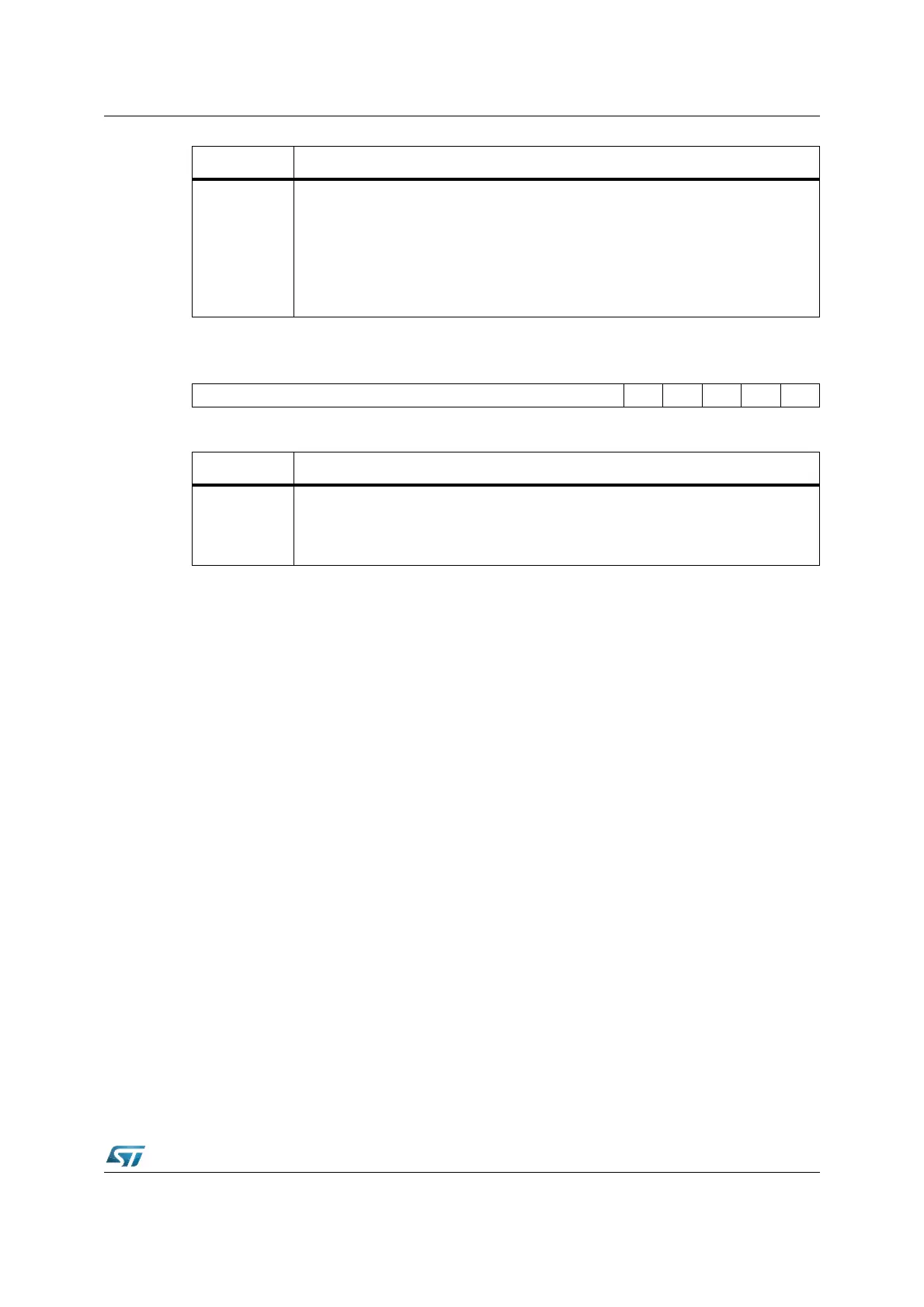
I2CCCR2 (EA0Eh) XBUS Reset Value: 0000h
Bit Function
D(7:0)
8-bit Data Register
These bits contain the received byte or the byte to be transmitted on the bus.
– Transmitter mode: Byte transmission starts automatically when the software
writes in the I2CDR register.
– Receiver mode: The first data byte is received automatically in the I2CDR register
using the least significant bit of the address. Then, the following data bytes are
received one by one after reading the I2CDR register.
1514131211109876543210
– CC11 CC10 CC9 CC8 CC7
RW RW RW RW RW
Bit Function
CC(11:7)
Additional 5-bit clock divider
These bits along with those of the Clock Control Register I2CCCR1 select the speed
of the bus (f
SCL
) depending on the I
2
C mode. They are not cleared when the
interface is disabled (PE
= 0)