CAN modules UM0404
430/564 DocID13284 Rev 2
IFx command request registers
A message transfer is started as soon as the CPU has written the message number to the
Command Request Register. With this write operation the Busy bit is automatically set to
‘1’. After a wait time of 3 to 6 CAN clock periods, the transfer between the Interface Register
and the Message RAM has completed and the Busy bit is set back to zero.
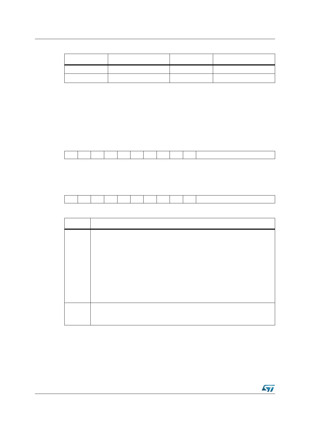
CAN1IF1CR (EF10h) XBUS Reset Value: 0001h
CAN2IF1CR (EE10h) XBUS Reset Value: 0001h
CAN1IF2CR (EF40h) XBUS Reset Value: 0001h
CAN2IF2CR (EE40h) XBUS Reset Value: 0001h
Note: When a Message Number that is not valid is written into the Command Request Register,
the Message Number will be transformed into a valid value and that Message Object will be
transferred.
CAN Base + 0x22 IF1 Data B 1 CAN Base + 0x52 IF2 Data B 1
CAN Base + 0x24 IF1 Data B 2 CAN Base + 0x54 IF2 Data B 2
1514131211109876543210
Busy --------- Message Number
R RW
1514131211109876543210
Busy --------- Message Number
R RW
Bit Function
Message
Number
Message Number
’00h’: Not a valid Message Number, interpreted as 20h.
’01h’: Valid Message Number, the Message Object in the RAM is selected for data
transfer.
’02h’: Valid Message Number, the Message Object in the RAM is selected for data
transfer.
’20h’: Valid Message Number, the Message Object in the RAM is selected for data
transfer.
’21h’: Not a valid Message Number, interpreted as 01h.
’22h’: Not a valid Message Number, interpreted as 02h.
’3Fh’: Not a valid Message Number, interpreted as 1Fh.
Busy
Busy Flag
’0’: Reset to zero when read/write action has finished.
’1’: Set to one when writing to the IFx Command Request Register.
Table 61. IF1 and IF2 message interface register sets
Address IF1 register set Address IF2 register set