DocID13284 Rev 2 501/564
UM0404 System reset
Note: The selected number of CS signals cannot be changed via software after reset.
Segment address lines: P0H.3 - P0H.4
Pins P0H.4 and P0H.3 (SALSEL) define the number of active segment address lines during
reset. This determines which pins of Port4 are used as address line or as I/O line. The two
bits are latched in register RP0H.
Depending on the system architecture the required address space is chosen and accessible
right from the start, so the initialization routine can directly access all locations without prior
programming.
The required pins of Port4 are automatically switched to address output mode.
Even if not all segment address lines are enabled on Port4, the ST10F276 internally uses its
complete 24-bit addressing mechanism.
This allows the restriction of the width of the effective address bus, while still deriving CS
signals from the complete addresses.
Default: 2-bit segment address (A17...A16) allowing access to 256 Kbytes.
Note: The selected number of segment address lines cannot be changed via software after reset.
Clock generation control: P0H.5 - P0H.6 - P0H.7
Pins P0H.7, P0H.6 and P0H.5 (CLKCFG) select the clock generation mode (on-chip PLL)
during reset. The oscillator clock either directly feeds the CPU and peripherals (direct drive)
or it is fed to the on-chip PLL which then provides the CPU clock signal (selectable multiple
of the oscillator frequency). These bits are latched in register RP0H (see previous
Section 23.9.1: System start-up configuration on page 496).
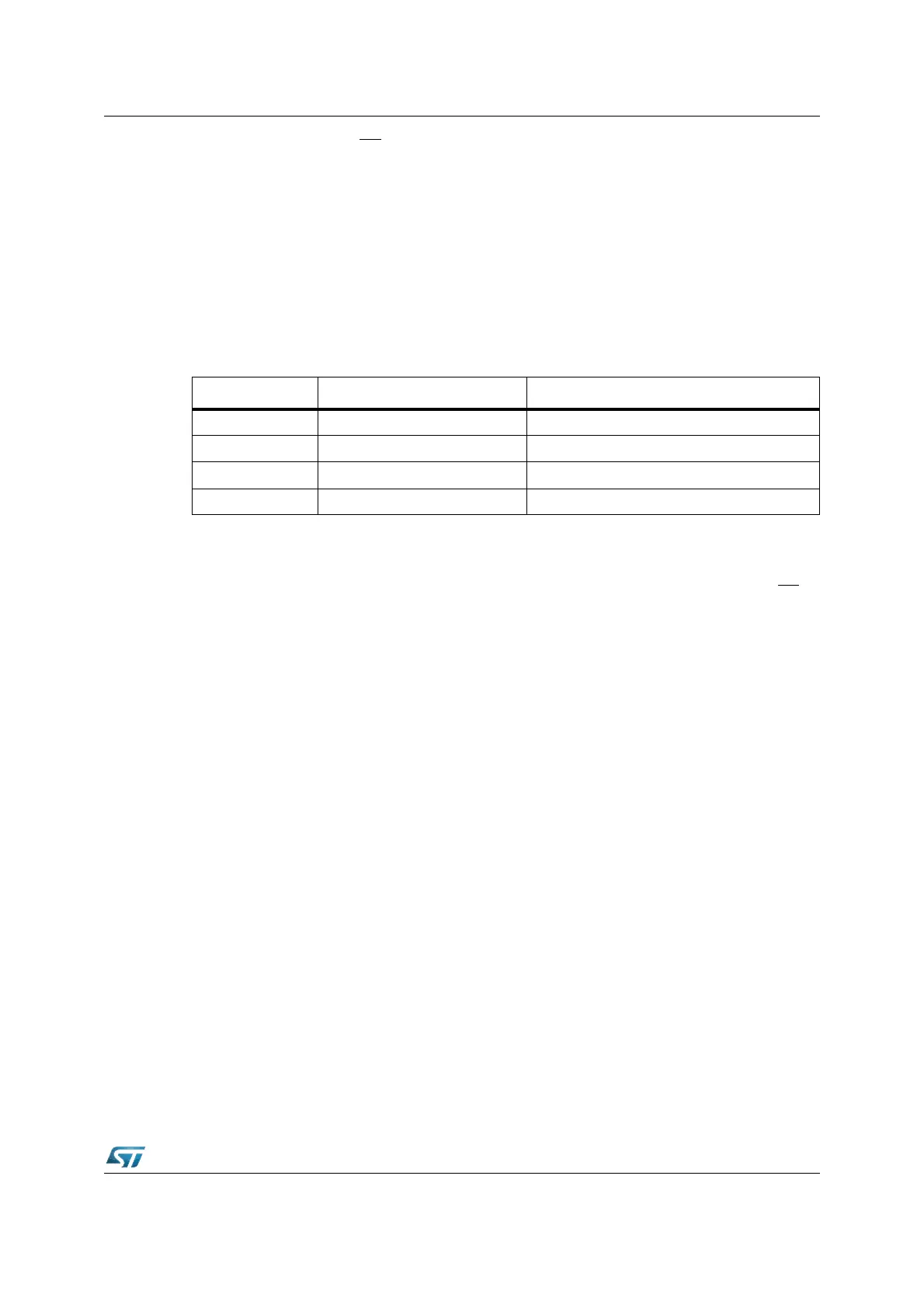
SALSEL Segment address lines Directly accessible address space
1 1 Two: A17...A16 256 Kbytes (Default without pull-downs)
1 0 Eight: A23...A16 16 Mbytes (Maximum)
0 1 None 64 Kbytes (Minimum)
0 0 Four: A19...A16 1 Mbyte