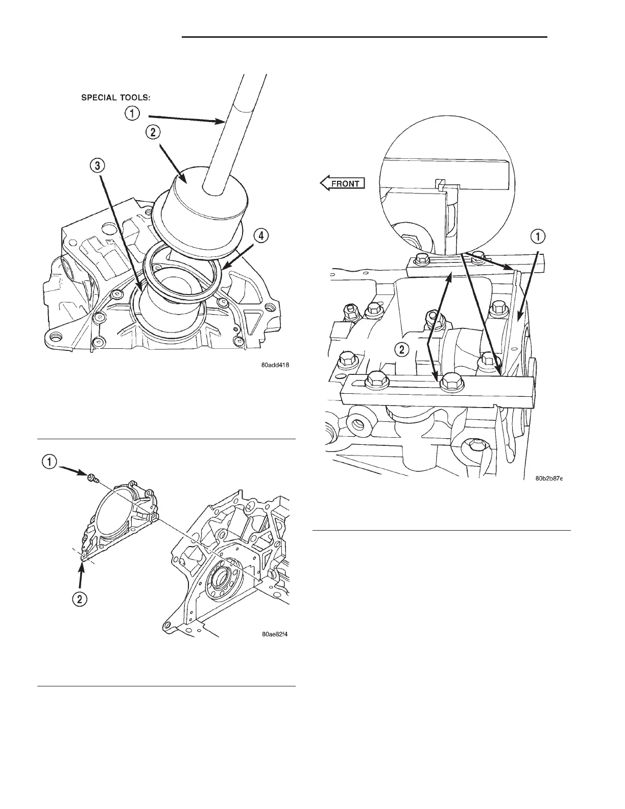
NOTE: Make sure the marking “3.2/3.5L” on Special
Tools 8225, is facing towards the cylinder block pan
rail surface (notch on tool is towards the seal
retainer).
(4) While applying firm pressure to the seal
retainer against Special Tools 8225 (Fig. 112), tighten
seal retainer screws to 12 N·m (105 in. lbs.).
(5) Install crankshaft rear oil seal and oil pan.
Refer to procedures in this section.
CRANKSHAFT MAIN BEARINGS
Bearing caps are not interchangeable and are
marked to insure correct assembly (Fig. 113). Upper
and lower bearing halves are NOT interchangeable.
CRANKSHAFT MAIN JOURNALS
The crankshaft journals should be checked for
excessive wear, taper and scoring. Limits of taper or
out-of-round on any crankshaft journals should be
held to 0.015 mm (0.0006 in.). Journal grinding
should not exceed 0.305 mm (0.012 inch.) under the
standard journal diameter. DO NOT grind thrust
faces of Number 2 main bearing. DO NOT nick crank
pin or bearing fillets. After grinding, remove rough
Fig. 110 Crankshaft Rear Seal—Installation
1 – C-4171 HANDLE
2 – 6926–2 INSTALLER
3 – 6926–1 GUIDE
4 – SEAL
Fig. 111 Oil Seal Retainer
1 – SCREWS (7)
2 – SEAL RETAINER
Fig. 112 Rear Crankshaft Seal Retainer Alignment
1 – SEAL RETAINER
2 – SPECIAL TOOLS 8225
9 - 130 3.2/3.5L ENGINE LH
REMOVAL AND INSTALLATION (Continued)