(4) Lubricate and install lower bearing half and
main cap Tighten bolts finger tight.
(5) For installing thrust washers at the No. 2 main
bearing location, use the following procedure:
(a) Move crankshaft forward to limit of travel.
Lubricate and install the front thrust washer by
rolling the washer onto the machined shelf
between the No. 2 upper main bulk head and
crankshaft thrust surface (Fig. 116).
(b) Move crankshaft rearward to limit of travel.
Lubricate and install the rear thrust washer by
rolling the washer onto the machined shelf
between the No. 2 upper main bulk head and
crankshaft thrust surface.
The main bearing cap bolts must be tightened in
the proper sequence. First the inner main cap bolts,
secondly the windage tray bolts, lastly the main cap
tie (horizontal) bolts.
(6) Install each main bearing cap and tighten
inner bolts finger tight.
(7) Tighten inner main bearing cap bolts to 20 N·m
+ 1/4 turn (15 ft. lbs. + 1/4 turn).
(8) Measure crankshaft end play. Refer to Service
Procedures in this section.
(9) Install windage tray. Lubricate bolts with
engine oil and tighten to 27 N·m + 1/4 turn (20 ft.
lbs. + 1/4 turn).
(10) Install the main cap tie (horizontal) bolts and
tighten to 28 N·m (250 in. lbs.).
(11) Install oil pump pick-up tube and oil pan.
(12) Fill engine crankcase with proper oil to cor-
rect level.
OIL FILTER
NOTE: When servicing the oil filter, avoid deform-
ing the filter can. Install the remove/install tool band
strap against the base lock seam. The lock seam
joining the can to the base is reinforced by the
base plate.
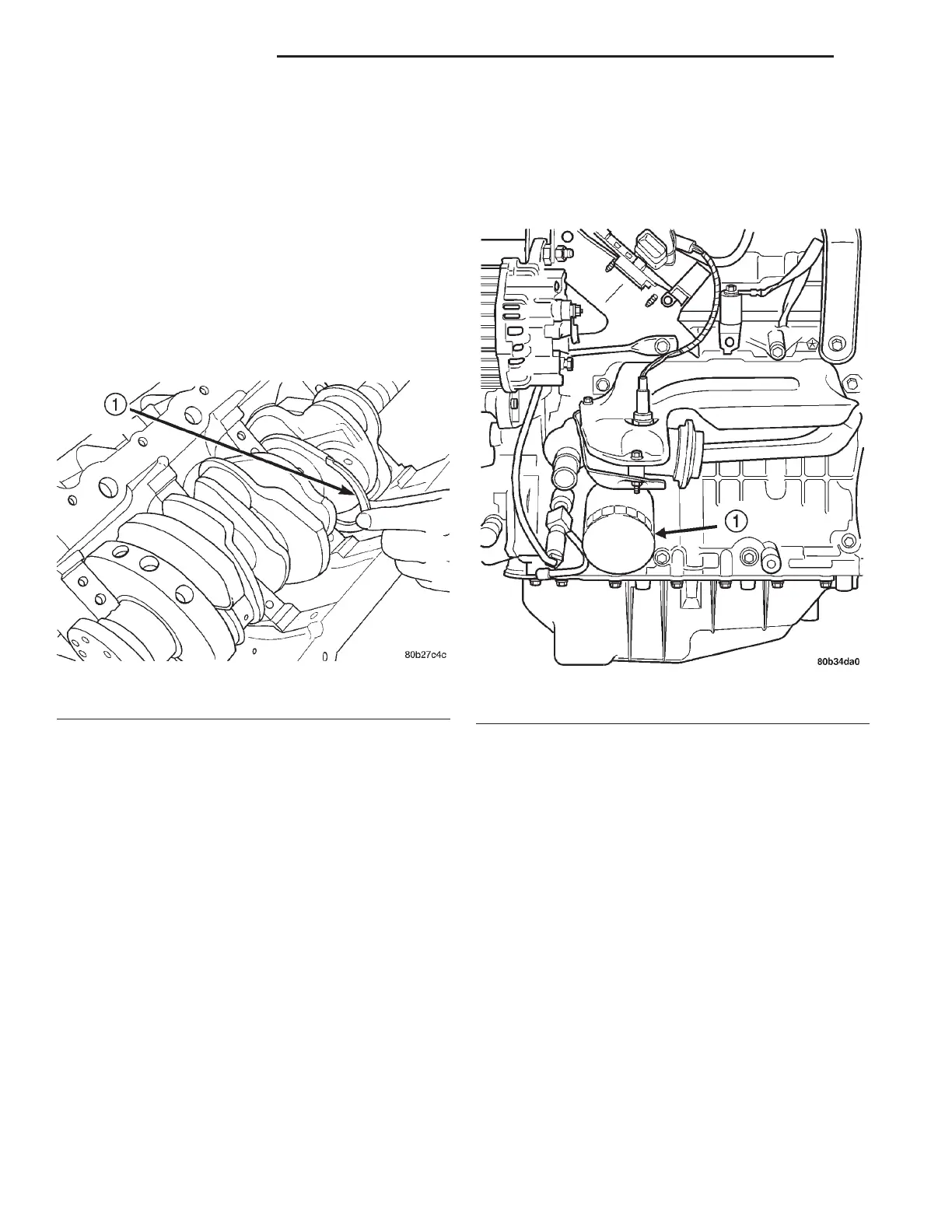
(1) Using a suitable oil filter wrench, unscrew fil-
ter from base and discard (Fig. 117).
(2) Wipe base clean, then inspect gasket contact
surface.
(3) Lubricate gasket of new filter with clean
engine oil.
(4) Install and tighten filter to 20 N·m (15 ft. lbs.)
of torque after gasket contacts base. Use filter
wrench if necessary.
(5) Start engine and check for leaks.
OIL PUMP
REMOVAL
It is necessary to remove the oil pan, oil pickup
and oil pump body to service the oil pump rotors. The
oil pump pressure relief valve can be serviced by
removing the oil pan.
(1) Drain cooling system and remove fan module.
Refer to COOLING SYSTEM for procedures.
(2) Remove the accessory drive belts. Refer to
COOLING SYSTEM for procedure.
(3) Remove the crankshaft damper and timing belt
covers. Refer to procedures in this section.
Fig. 116 Thrust Washer Installation
1 – FRONT THRUST WASHER
Fig. 117 Oil Filter
1 – OIL FILTER
9 - 132 3.2/3.5L ENGINE LH
REMOVAL AND INSTALLATION (Continued)