(4) Remove back panel from seat back frame.
INSTALLATION
CAUTION: Always install new push pins in the
upper mounting location of back panel. Failure to
do so could adversely affect the airbag system.
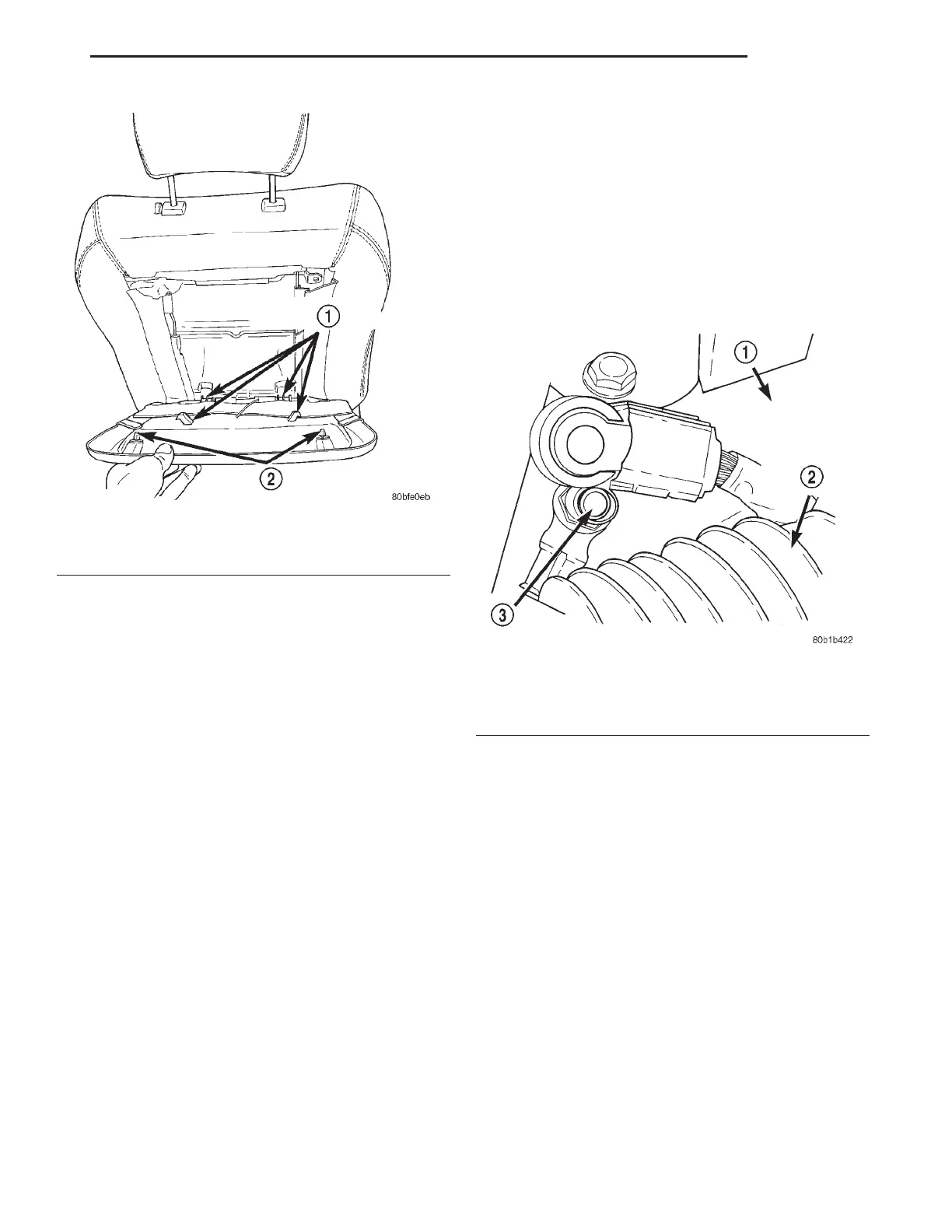
(1) Starting at the bottom, line-up back panel
retaining tabs and new push pins. Then push sharply
to snap in place.
(2) Check back panel fit and finish. Run a finger
down the sides of back panel to be certain panel fits
tight to the rear of trim cover.
CAUTION: Be certain seat back panel is properly
secured in place. Failure to do so could adversely
affect the airbag system.
(3) Connect the negative battery cable.
FRONT SEAT BACK - AIRBAG EQUIPPED
REMOVAL
(1) Position seat forward enough to allow removal
of the rear seat track to floor pan bolts.
WARNING: DISCONNECT AND ISOLATE THE NEG-
ATIVE BATTERY CABLE REMOTE TERMINAL
BEFORE BEGINNING ANY FRONT SEAT REMOVAL
OR INSTALLATION PROCEDURE. THIS WILL DIS-
ABLE THE AIRBAG SYSTEM. FAILURE TO DISCON-
NECT THE BATTERY COULD RESULT IN
ACCIDENTAL AIRBAG DEPLOYMENT AND POSSI-
BLE PERSONAL INJURY.
WARNING: ONCE THE NEGATIVE CABLE IS DIS-
CONNECTED WAIT FOR 2 MINUTES BEFORE
REMOVING ANY AIRBAG SYSTEM COMPONENTS.
(2) Disconnect and isolate the remote negative bat-
tery cable (Fig. 8).
(3) Remove the front seat from the vehicle. Refer
to the procedure in this group.
(4) Remove the front seat cushion side shields.
Refer to the procedure in this group.
(5) Disengage push pin and disconnect the yellow
airbag wire harness connector located on the bottom
of the seat cushion pan (Fig. 9).
(6) Disengage push pin and disconnect the heated
seat element wire connector also located on the cush-
ion pan.
(7) Remove bolts attaching recliner to seat back
cushion frame (Fig. 10).
(8) Remove inboard and outboard pivot bolts con-
necting the seat cushion to the seat back.
(9) Feed wire harnesses between the seat track
and cushion pan and remove seat back from seat
cushion.
(10) Remove necessary components from seat back
for reuse if possible. Refer to the procedures in this
group.
Fig. 7 Back Panel Mounting
1 – BACK PANEL RETAINING TABS
2 – BACK PANEL RETAINING PUSHPINS
Fig. 8 Negative Battery Cable Remote Terminal
1 – RIGHT STRUT TOWER
2 – AIR CLEANER INLET TUBE
3 – REMOTE TERMINAL
LH BODY 23 - 5
REMOVAL AND INSTALLATION (Continued)
2000 LHS, 300M, CONCORDE AND INTREPID