Closed-loop Flow Control
ATM Services Configuration Guide for CBX 3500, CBX 500, GX 550, and B-STDX 9000 1/19/055-7
Beta Draft Confidential
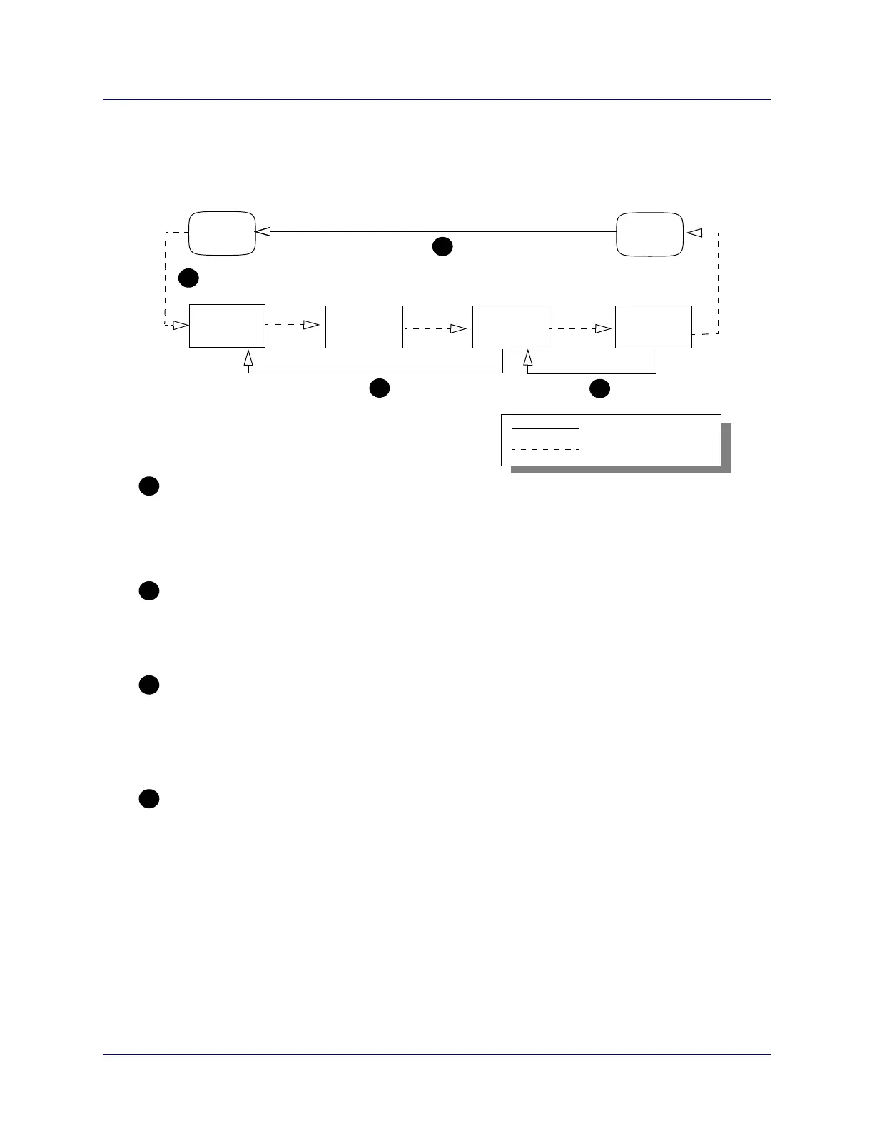
Figure 5-2 shows hop-by-hop, closed-loop flow control between four CBX 500
switches. The flow control loops are shown as solid lines. The data paths are shown as
dotted lines.
Figure 5-2. Closed-loop Flow Control
Switch 1
Switch 4Switch 3Switch 2
User 1
User 2
1
2
3
4
Data Path
=
Flow Control Loops
=
1
2
3
4
End-to-End User Control Loops
Different Logical Port Types on the Same IOM
Switches Without Flow Control Loops
Rate Control at the Output Switch
The ATM FCP supports different types of flow control loops on the same IOM. User 1 has a
User-to-Network Interface (UNI) connection. Switch 2 has a trunk connection to a different port on the
same IOM in Switch 1. Enabling and disabling of loop control is provisioned per port.
End-to-end user flow control loops are “outer” loops. The switches do not change their cell rates in
response to this flow control loop. Rather, they mark the congestion indication (CI) and no increase (NI)
bits based on the local congestion state, as defined in the ATM Forum’s Traffic Management
Specification, Version 4.0.
Switch 2 does not generate or terminate flow control loops to the other switches. Switch 2 generates a
forward notification of congestion to Switch 3. Explicit forward congestion indication (EFCI) marking can
be configured on a CBX 500 switch through Navis EMS-CBGX. When Switch 2 marks EFCI in the data
cells, Switch 3 can be configured to include EFCI notification in the decision of the backward notification
to Switch 1.
Switch 4’s cell rate fills the available bandwidth and is adjusted based on local congestion. The flow
control loop between Switch 4 and User 2 can be configured as either BCM or CCRM termination.
If configured as BCM, Switch 4 will adjust rates according to the port congestion. If configured as
CCRM, Switch 4 will perform traffic shaping to the initial cell rate (ICR) of each VC.