Beta Draft Confidential
21-101/19/05 ATM Services Configuration Guide for CBX 3500, CBX 500, GX 550, and B-STDX 9000
Configuring PNNI Routing
PNNI Routing Protocol Overview
PNNI Routing Example
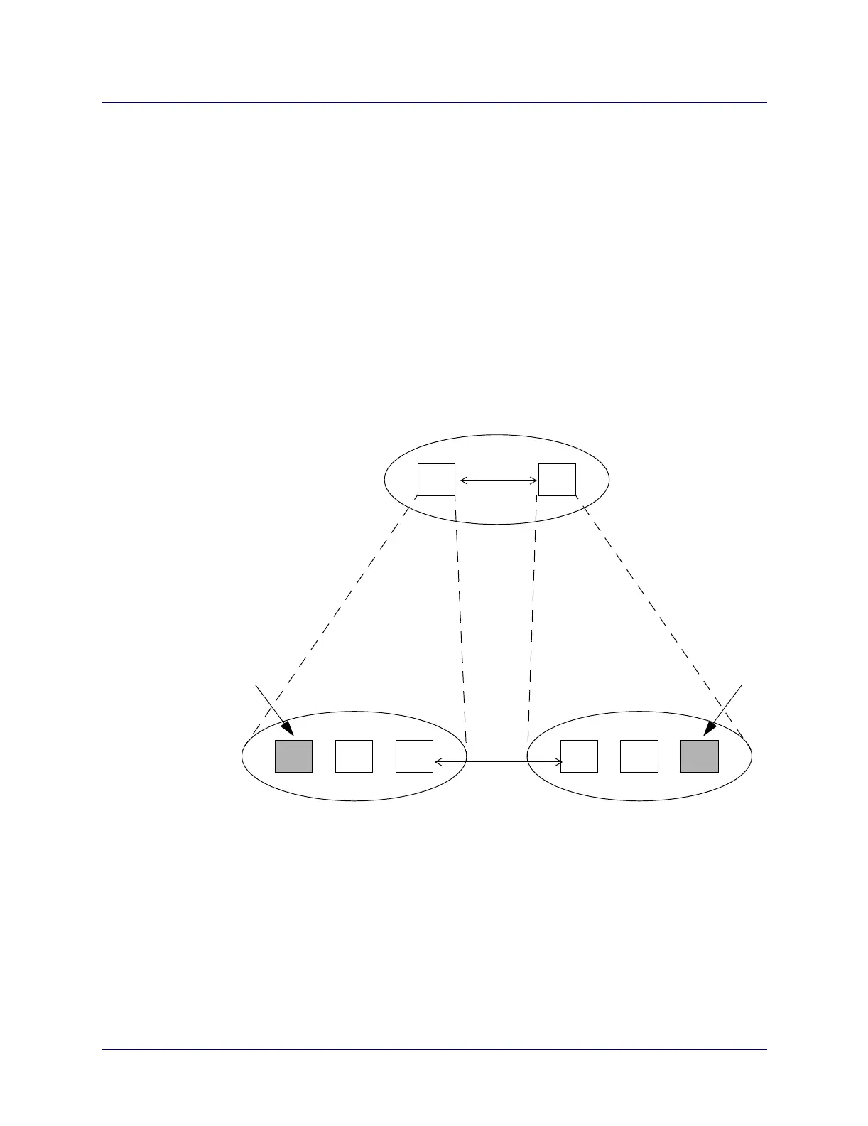
Figure 21-2 shows a simple two-tiered PNNI routing hierarchy, with six lowest-level
nodes divided into two child peer groups (PG1 and PG2). The LGNs that are the
parents of each of the child peer groups form a top-tier peer group (PG3).
Peer groups may contain both LGNs and lowest-level nodes. For example, in
Figure 21-2, a lowest-level node could also be a member of PG3. A node’s
membership within the hierarchy is determined by the network configuration. In other
words, the network administrator configures the hierarchical structure.
Neighboring nodes (LGN or lowest-level node) within a peer group exchange
information to synchronize their topology databases. The topology database contains
information about the peer group in which a node resides and information that allows
the node to reach destinations in other peer groups. A node receives information about
the network beyond the peer group from its PGL.
Figure 21-2. Two-Tiered PNNI Routing Hierarchy Example
N N N N N N
LGN LGN
Legend
N = Lowest-level Node
LGN = Logical Group Node
PG = Peer Group
PG1
PG2
PG3
PGL
PGL = Peer Group Leader
PGL