Beta Draft Confidential
21-301/19/05 ATM Services Configuration Guide for CBX 3500, CBX 500, GX 550, and B-STDX 9000
Configuring PNNI Routing
PNNI Policy-based Routing
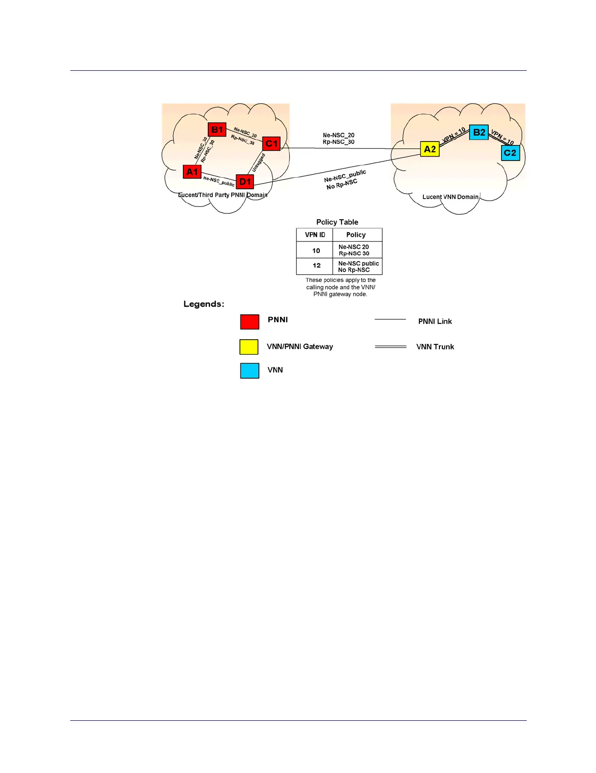
Figure 21-7. VNN-PNNI Policy-based Routing Example
Figure 21-7 displays how a call may be sent to/from a VNN network, through the
gateway switch (A2), to/from a PNNI network.
In the example, a PVC/SPVC is configured from A1 to C2. As part of the
configuration, a policy constraint is defined and assigned to this call. The policy
constraint has the following policy constraints:
• Translation of a VPN circuit with public overflow disabled:
require (single (Ne-NSC 20); single (Rp-NSC 30))
• Translation of VPN circuit with public overflow enabled:
require (single (Ne-NSC 20); single (Rp-NSC 30)) and
require (LOR (Ne-NSC 20, Ne-NSC public); LOR (Rp-NSC 30, bare))
The call request process on node A1 will proceed as follows:
• On node A1 (call originating point), since this is the call-originating point,
Navis EMS-CBGX provides the capability to configure the policy constraint and
associate policy constraint with a particular circuit.