5-81/19/05 ATM Services Configuration Guide for CBX 3500, CBX 500, GX 550, and B-STDX 9000
CCRM Closed-loop Flow Control
Beta Draft Confidential
CCRM Closed-loop Flow Control
Lucent’s closed-loop, flow control architecture can use CCRM cells to notify
other FCPs of network congestion or availability. CCRM cells are normally generated
at the RM cell generation rate if the circuit is active.
CCRM Closed-loop Flow Control on a Trunk
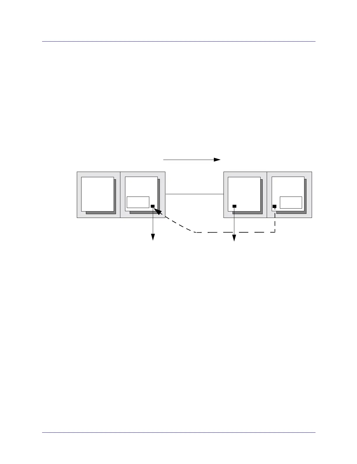
Figure 5-3 shows an example of CCRM closed-loop flow control between two
CBX 500 switches.
Figure 5-3. CCRM Closed-loop Flow Control
On Switch B, the FCP in IOM 2 generates RM cells to control the rate of data
transmitted by IOM 2 on Switch A. IOM 2 on Switch B also determines the type of
RM cell to generate by looking at the logical port setting on IOM 1 on Switch B.
ATM FCP
CBX 500 SWITCH A
ATM FCP
CBX 500 SWITCH B
Data Flow
Trunk Line
Feedback Flow
Configured to terminate
CCRM cells on the logical port
Configured to generate
CCRM cells on the logical port
CBX 500
I/O Module
2
CBX 500
I/O Module
1
CBX 500
I/O Module
2
CBX 500
I/O Module
1