Beta Draft Confidential
10-141/19/05 ATM Services Configuration Guide for CBX 3500, CBX 500, GX 550, and B-STDX 9000
Configuring ATM PVCs
Defining a Point-to-Point Circuit Connection
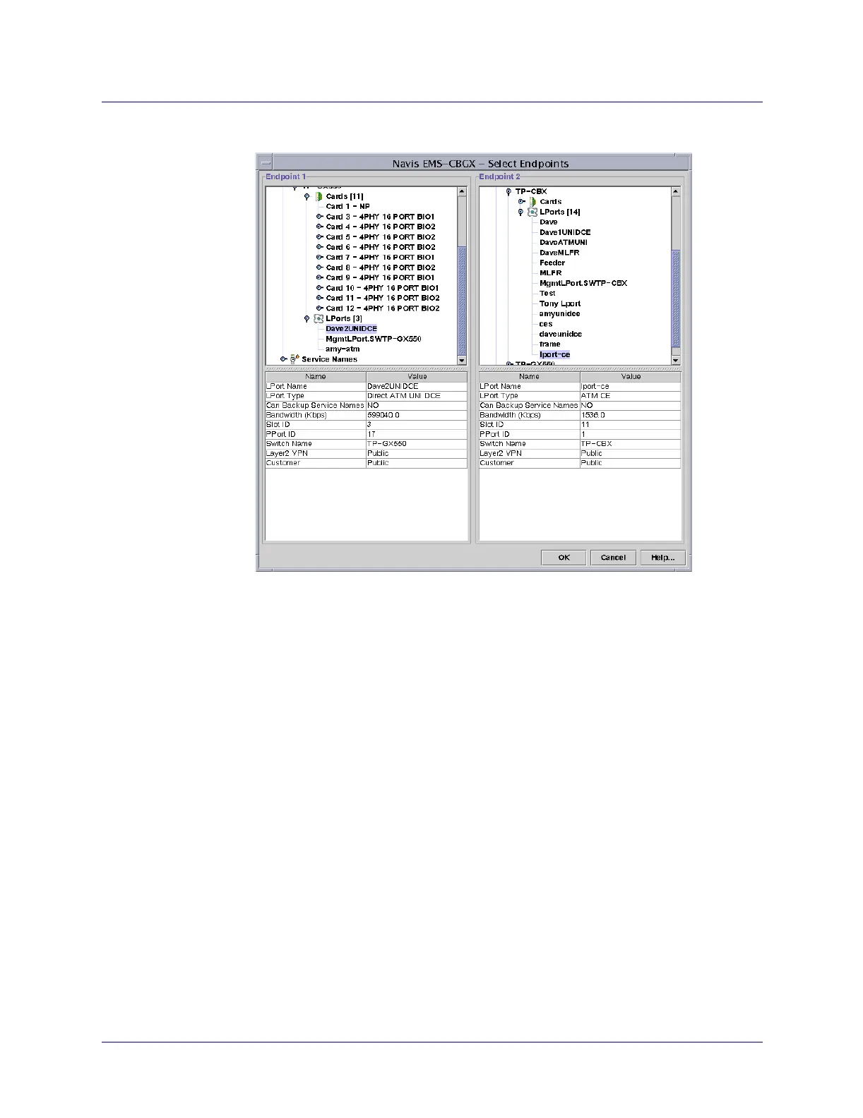
Figure 10-4. Select Endpoints Dialog Box
4. Define the circuit endpoints using the following instructions, depending on
whether you are defining a standard circuit, or fault-tolerant or resilient LMI PVC
connection.
For a Standard Circuit Configuration
a. Expand the Switches node, select a switch, and use the Cards or LPorts node
to select Endpoint 1.
b. Repeat step a to select the name of the logical port for Endpoint 2. Note that if
you enable the Select Layer2 VPN Customer View feature (see page 13-8),
only logical ports that belong to the VPN or customer you select appear in this
list.
c. Continue with step 5.
For a Fault-tolerant PVC Connection
For more information about fault-tolerant PVCs, see Chapter 14, “Configuring
Fault-tolerant PVCs.”
a. Expand the Service Names node, and select a service name from the list.