Beta Draft Confidential
10-661/19/05 ATM Services Configuration Guide for CBX 3500, CBX 500, GX 550, and B-STDX 9000
Configuring ATM PVCs
Configuring Frame Relay-to-ATM Interworking Circuits
FRF.5 Attributes
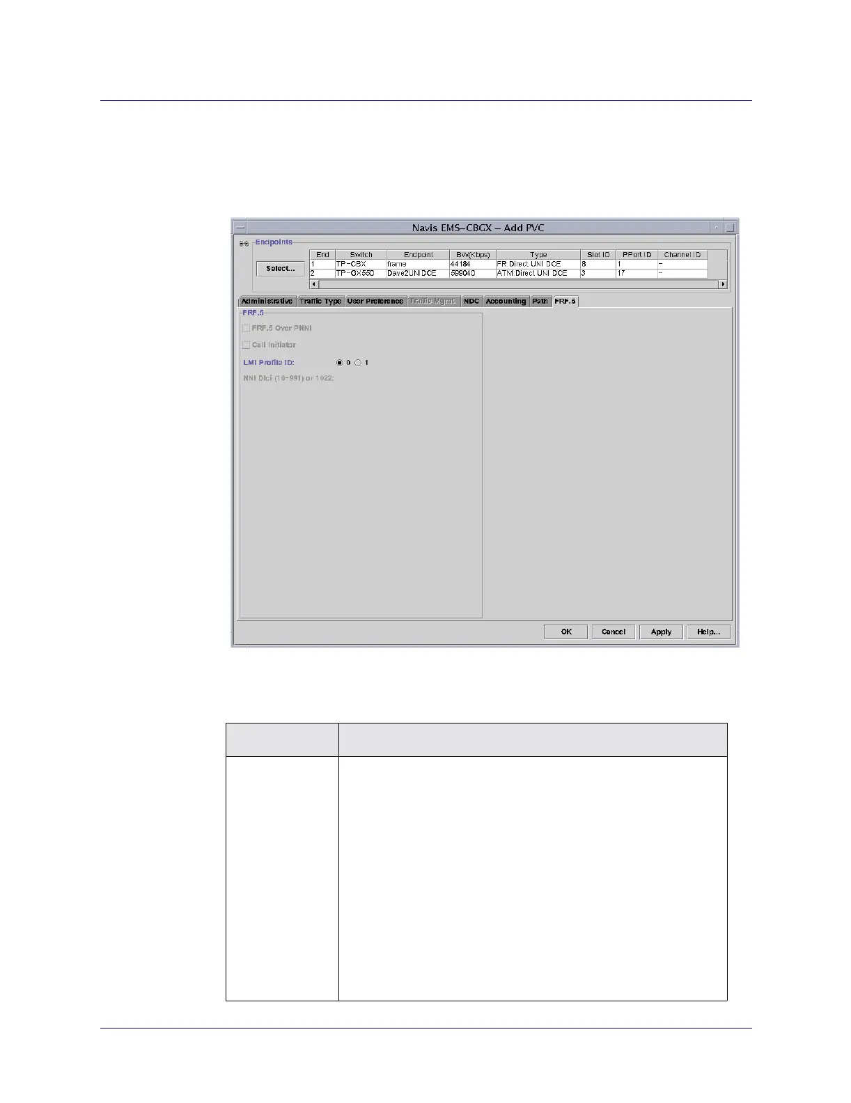
Select the FRF.5 tab in the Add PVC dialog box (Figure 10-14) and complete the
fields, as described in Table 10-13.
Figure 10-14. Add PVC: FRF.5 Tab (FR-ATM)
Table 10-14. Add PVC: FRF.5 Tab Fields
Field Action/Description
LMI Profile ID For a service interworking PVC (FRF.8), accept the default value
(0), which disables FRF.5.
For a network interworking PVC (FRF.5), select 1 to enable the
LMI profile for the circuit, and then enter the NNI DLCI value.
Note: The LMI profile for the network interworking PVC is
configured on a per-PVC basis using Q.933 Annex A as the LMI
protocol. However, when you configure the Frame Relay logical
port endpoint for this circuit, the link management protocol can be
set to any of the following protocols: Disable, LMI, Rev1, ANSI
T1.617 Annex D, CCITT Q.933 Annex A, or Auto Detect. See the
Frame Relay Services Configuration Guide for CBX 3500, CBX
500, and B-STDX 9000 for details about setting the link
management protocol attribute for a logical port.