Beta Draft Confidential
About SVCs
About Address Translation
ATM Services Configuration Guide for CBX 3500, CBX 500, GX 550, and B-STDX 9000 1/19/0516-15
Examples
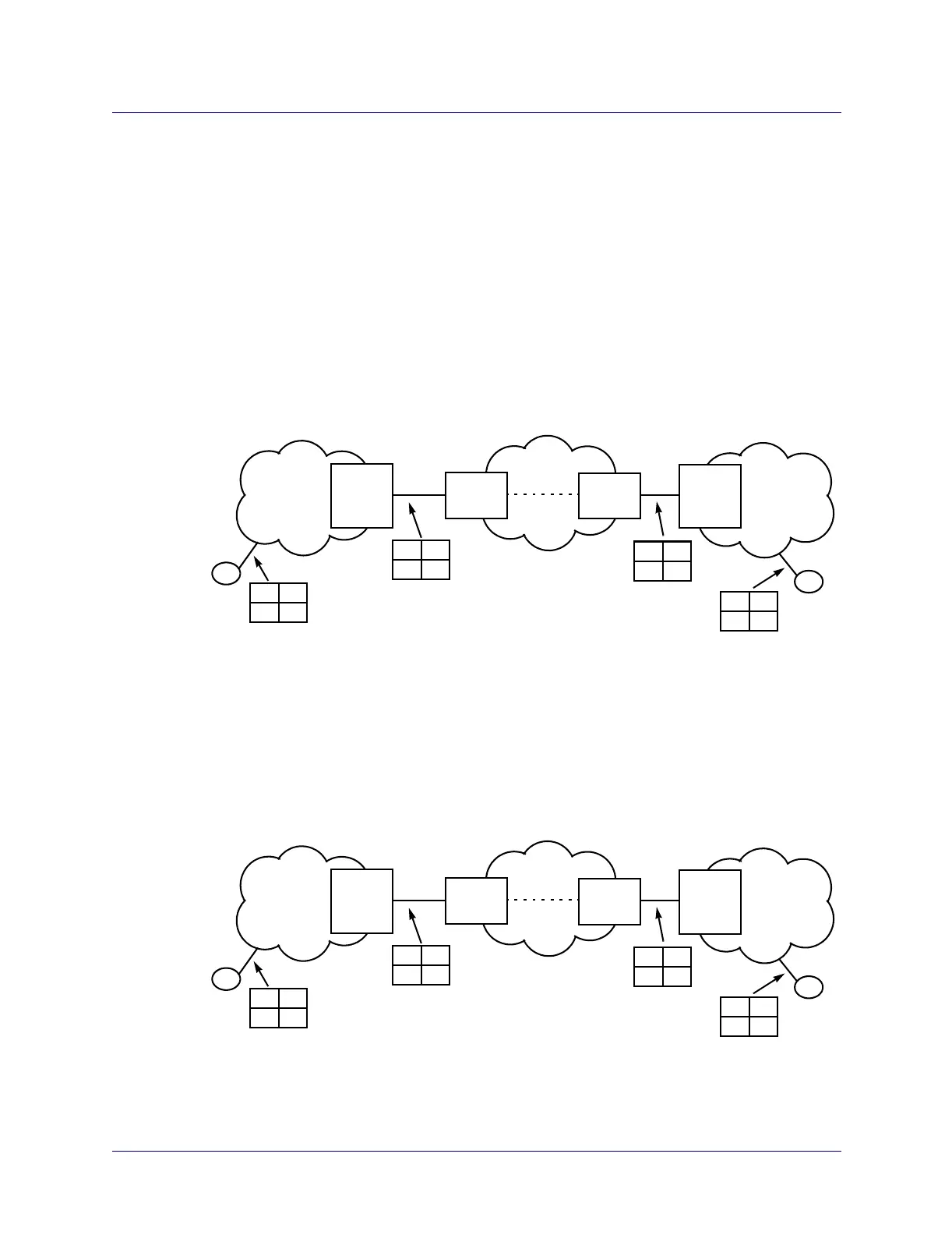
The following example diagrams show the state of the SETUP message calling party/
called party address and sub-address elements at various points along the connection.
The example diagrams represent the calling party and called party address and
sub-address elements as shown in Table 16-6.
\
Figure 16-5. State of Connection SETUP Message Address Elements (1)
Figure 16-6. State of Connection SETUP Message Address Elements (2)
Private
Network
Node
Public
ATM
Network
Address
X
Address
Y
Private
Network
Node
A
Example 1
AB
null
null
XY
AB
XY
AB
AB
null
null
- Egress tunneling enabled on Network 1’s egress port
- Local Gateway address X configured to a prefix on Network 1’s egress
- Remote Gateway address Y configured to a prefix on Network 1’s egress
Network
1
Network
2
- Ingress tunneling enabled on Network 2’s ingress port
port, and the prefix corresponds to B
port, and the prefix corresponds to B
B
Private
Network
Node
Public
ATM
Network
Address
X
Address
Y
Private
Network
Node
A
Example 2
AB
null
null
AY
B
AY
B
AB
null
null
- No Local Gateway address defined on egress port
null
null
- Egress tunneling enabled on Network 1’s egress port
- Ingress tunneling enabled on Network 2’s ingress port
- Remote Gateway address Y configured to a prefix on Network 1’s egress
port, and the prefix corresponds to B
Network
1
Network
2
B