If a customer complains that there is an issue with a plot they are printing, this standard template can be
printed and referred to by both the customer and HP as a single point of reference.
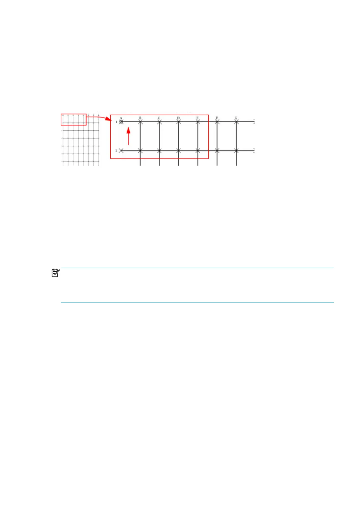
The plot consists of a 7x7 matrix of rectangular boxes. By default, each single rectangle corresponds to a DIN
A4 sheet size (210mm x 297). Based on this, the total printed plot length should be about 2.07 meter
(approx. 82”) and 1.47 meters (approx. 58”). However the actual dimensions will highly depend on what
settings have been defined for the Substrate Advance.
Each point in the matrix can be identified by means of a letter in the X axis and number in the Y axis. There is
an arrow in the plot close to the point ‘A1’ to show the printing direction.
The method of evaluating the geometric performance is the following:
1. Select an area on the matrix to evaluate for accuracy and dimensional integrity. The template is
designed so you can measure anything from an A4 sheet upwards to any probable dimension.
2. Place the printed plot on a flat surface. This will minimize any wrinkles before proceeding with the
process.
3. Find the vector length accuracy by selecting parallel vectors and/or figure distortion by measuring the
diagonals in the selected area.
4. Note the measurements to access the printer’s performance. It will help to keep the measured vectors
identified by using the name convention marked on the plot i.e. A1, A3. This makes it easier to identify
exactly the areas of the plot where the measurements were taken.
NOTE: To check whether a printer complies with the technical specifications, see the ‘Line accuracy’ section
in the printer’s data sheet.
After loading substrate, allow the substrate to stabilize before printing the plot. Some types of substrate
require up to 3 meters before they are stabilized.
Corrective action
1. Reload the substrate following the exact steps from the user’s guide.
2. In some cases, differences in the substrate advance along the scan axis could cause geometric defects.
Try adjusting the settings in the RIP. Adjust Vacuum level and Backtension levels. Be careful when
adjusting these settings, refer to the RIP supporting documentation for further details of this type of
adjustment.
Scan-axis check
This plot shows any defect in the Encoder Strip along the Scan Axis. To print this test plot go to Menu List > 2.
Image Quality Plot > 2.6 Scan Axis Check.
Any defects in the encoder strip can decrease the level of image quality of the printer, specifically in the area
where the encoder is defective. The defect is revealed by means of an interference or Vernier pattern that
spans the whole Scan Axis of the printer.
ENWW Scan-axis check 197
 Loading...


