6. Tighten all 7 fittings connecting the ink tube to the PIP module.
7. Refill the ink tube from which the PIP module has been replaced. See
3.3.3 Refill Ink Tubes on page 152.
8. Perform the PIP calibration process. See
3.4.2 Ink-Level Sensors Calibration on page 155.
9. Before installing the left cover, print a sample plot and make sure there is no ink leaking from the PIP
fittings.
Under-carriage protector assembly
Removal
WARNING! Turn off the printer and disconnect both power cords.
1. Remove the Right cover on page 246.
2. Remove the
Carriage assembly on page 370.
3. Remove the
Left cover on page 249.
4. Remove the
Encoder disc and sensor on page 385.
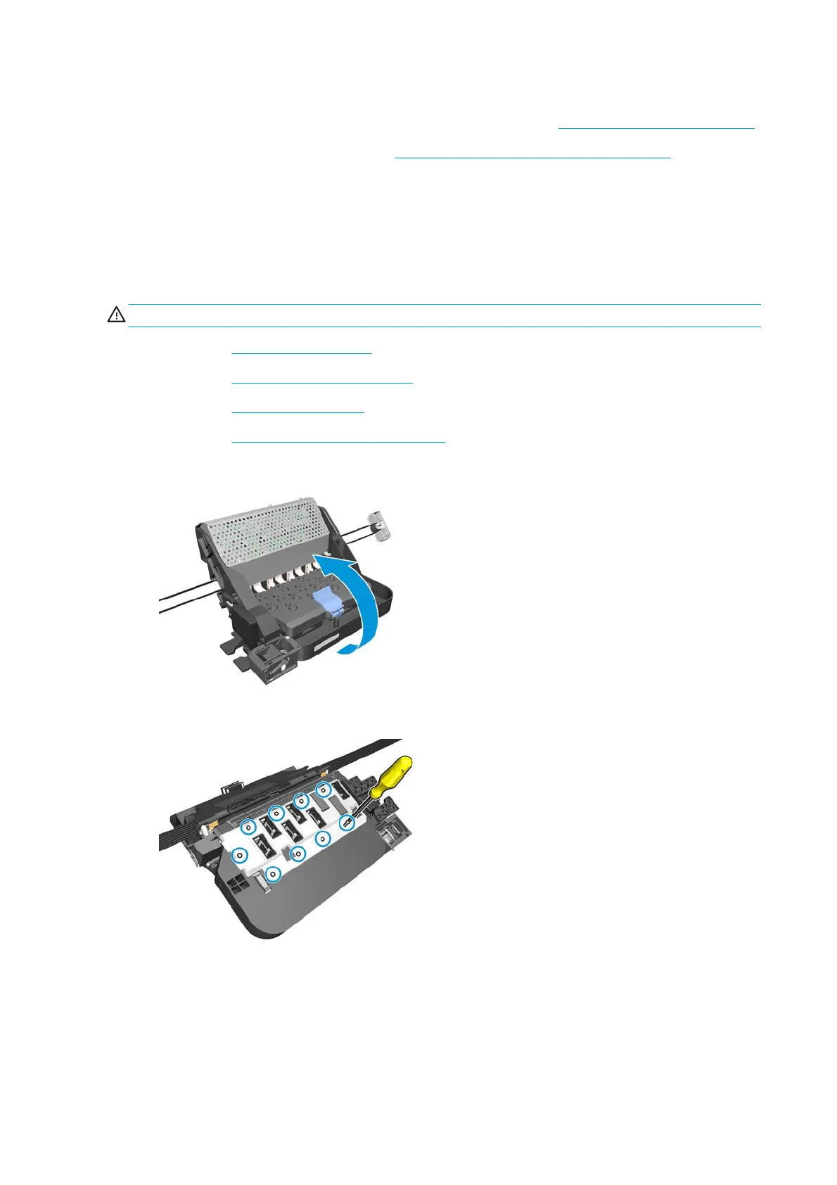
5. Turn the carriage assembly upside down to access the under-carriage protector assembly.
6. Remove nine T-8 screws that secure the under-carriage protector assembly to the carriage assembly.
330 Chapter 8 Removal and installation ENWW
 Loading...


